Euphonix System 5 Installation Guide System 5 Components
68
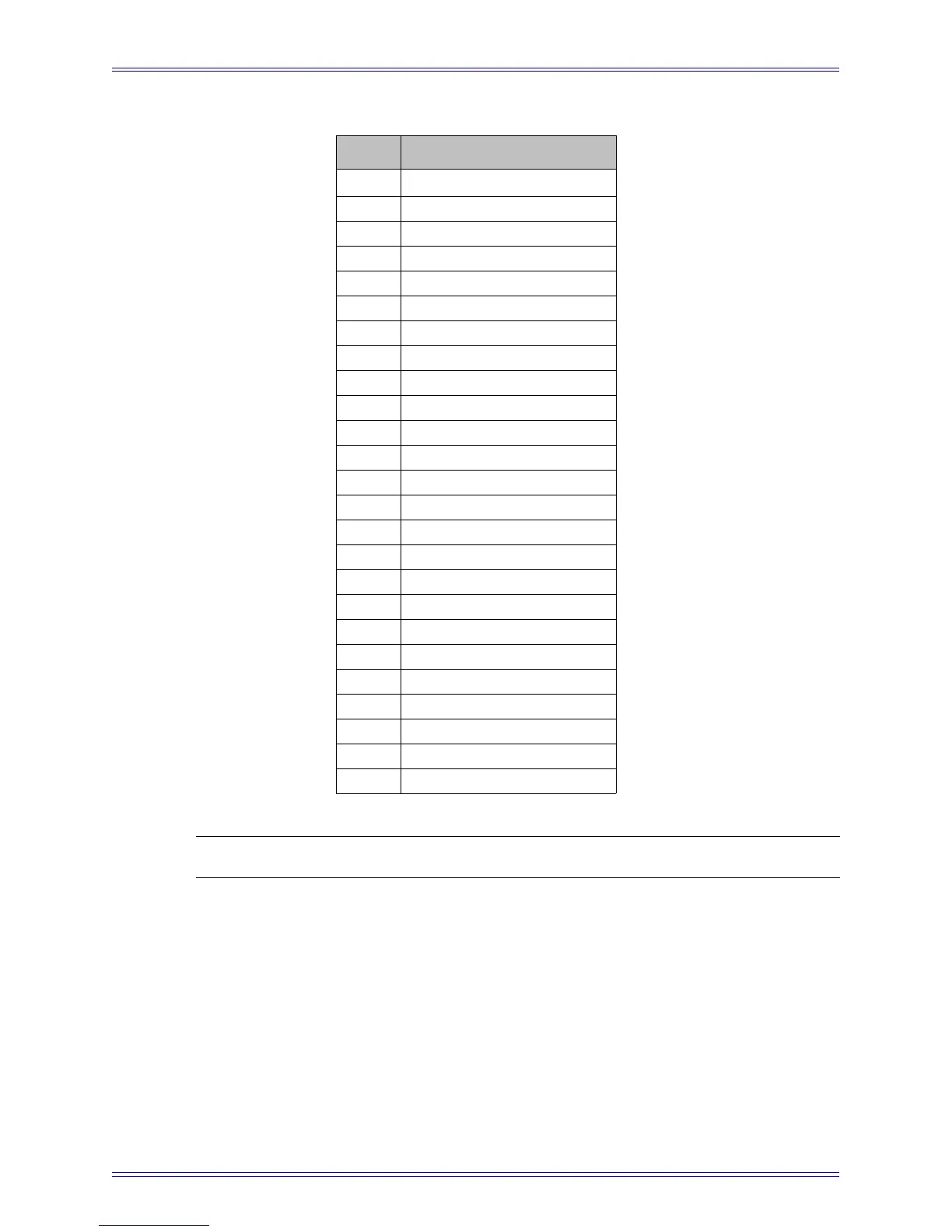
Table 3-7 AES/EBU DB-25 Pinout
NOTE: In and Out are from the FC7276’s perspective.
Pin Description
Pin 1 N/C
Pin 2 Channel 1 / 2 In (COLD)
Pin 3 Channel 3 / 4 In (GND)
Pin 4 Channel 3 / 4 In (HOT)
Pin 5 Channel 5 / 6 In (COLD)
Pin 6 Channel 7 / 8 In (GND)
Pin 7 Channel 7 / 8 In (HOT)
Pin 8 Channel 1 / 2 Out (COLD)
Pin 9 Channel 3 / 4 Out (GND)
Pin 10 Channel 3 / 4 Out (HOT)
Pin 11 Channel 5 / 6 Out (COLD)
Pin 12 Channel 7 / 8 Out (GND)
Pin 13 Channel 7 / 8 Out (HOT)
Pin 14 Channel 1 / 2 In (GND)
Pin 15 Channel 1 / 2 In (HOT)
Pin 16 Channel 3/ 4 In (COLD)
Pin 17 Channel 5 / 6 In (GND)
Pin 18 Channel 5 / 6 In (HOT)
Pin 19 Channel 7 / 8 In (COLD)
Pin 20 Channel 1 / 2 Out (GND)
Pin 21 Channel 1 / 2 Out (HOT)
Pin 22 Channel 3 / 4 Out (COLD)
Pin 23 Channel 5 / 6 Out (GND)
Pin 24 Channel 5 / 6 Out (HOT)
Pin 25 Channel 7 / 8 Out (COLD)