Jumpers and connectors
Issue G 25
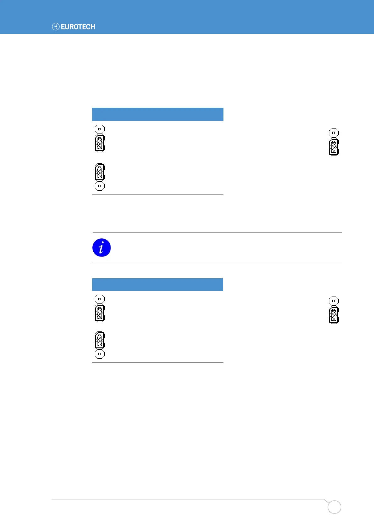
JP1 PCI – PCI Grant/PCI auxiliary power selection
Used to select the functionality of PCI slot pin A14. There are two options available: 3.3V
PCI auxiliary voltage routed to the PCI slot, or GNT4 signal. GNT4 is made available to
support a third PCI slot (via a riser card); the default jumper setting should be used with a
two-slot PCI riser.
JP1 PCI
Description
3.3V PCI Auxiliary power to
PCI slot.
GNT4 to PCI slot.
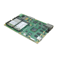
JP1 Firmware hub – BIOS write protection
To enable BIOS write protection the jumper must be placed in position 2-3.
BIOS ECSD data cannot be updated when the write protect is in place. Any
devices added to the system with write protection enabled will not be reported by
the BIOS.
JP1 FWH Description
BIOS firmware hub writeable.
BIOS firmware hub write
protected.
Default setting:
Default setting: