APOLLO user manual
Issue G
28
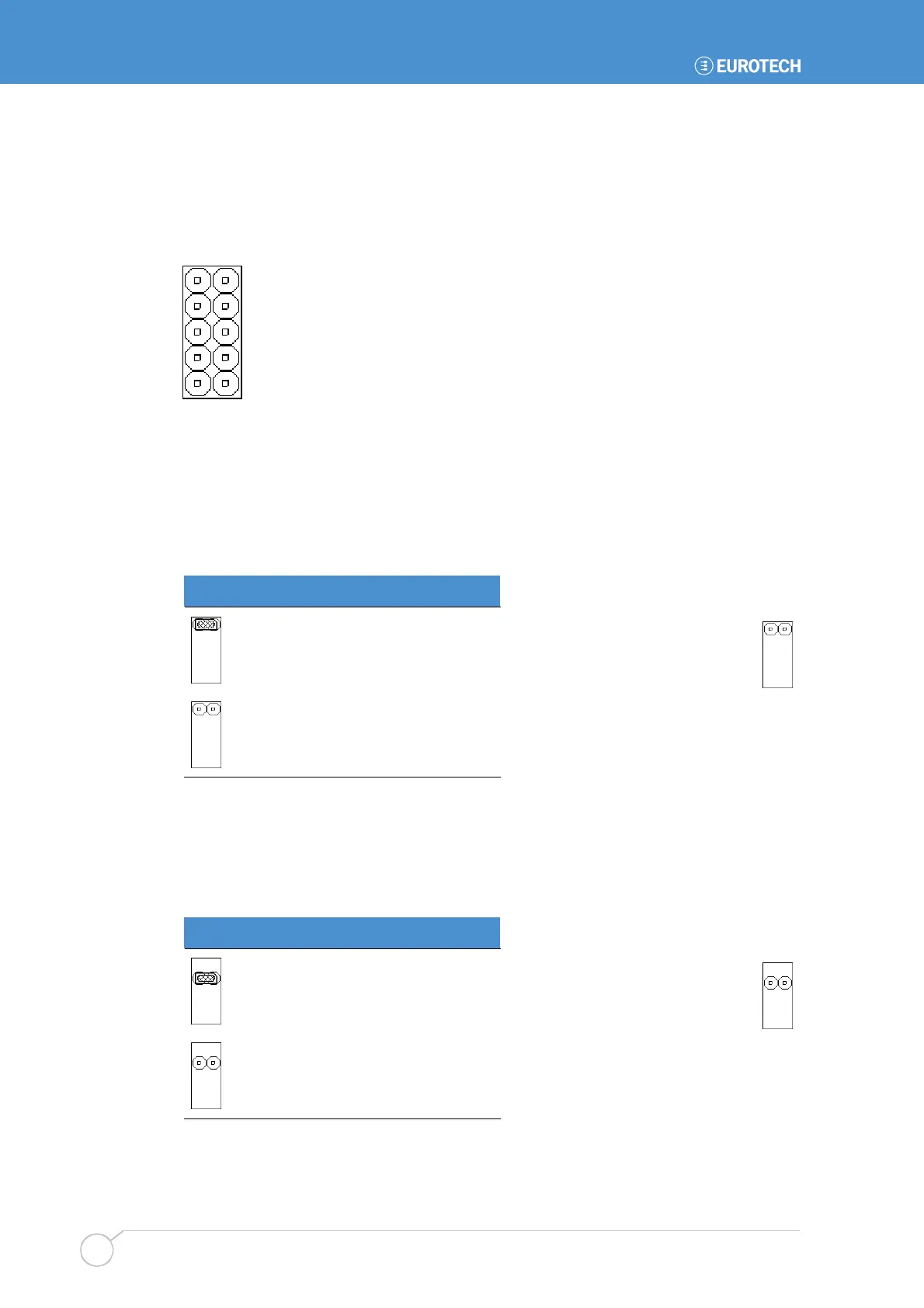
JP2 on APOLLO V2Ix – User-configurable, CMOS reset and tamper detect
This consists of five individual jumper positions. Two of these are user-configurable
(USR1 and USR2). The third (CMOS) is used to clear the battery backed CMOS memory,
whilst the fourth (TPM) provides a tamper detect option. This is illustrated in the following
diagram:
The individual positions are explained further in the following sections.
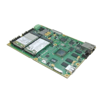
APOLLO V2Ix: USR1 – User-defined jumper one
This jumper is user-configurable and can be used by an application program to determine
a configuration setting. The status of this jumper is read through the firmware hub general
purpose inputs, located at memory location FFBC0100H bit 1. This is an 8-bit read and a
read-only memory location; writing to this bit has no effect.
USR1 Description
Bit is low ‘0’.
Bit is high ‘1’.
APOLLO V2Ix:- USR2 – User-defined jumper two
This jumper is user-configurable and can be used by an application program to signify a
configuration setting. The status of this jumper is read through the firmware hub general
purpose inputs, located at memory location FFBC0100H bit 2. This is an 8-bit read and a
read-only memory location; writing to this bit has no effect.
USR2 Description
Bit is low ‘0’.
Bit is high ‘1’.
JP2 – APOLLO V2Ix
Default setting:
Default setting: