5
HOMEDEPOT.COM
Please contact 1-844-883-1872 for further assistance.
Installation
WELL PIPE INSTALLATION
Use the installa
tion methods provided in this chapter that match with your water source.
CASED WELL/DUG WELL INSTALLATION
1. Inspect the
foot or in line check valve to be sure it works
freely. Inspect the strainer to be sure it is clean and
secure.
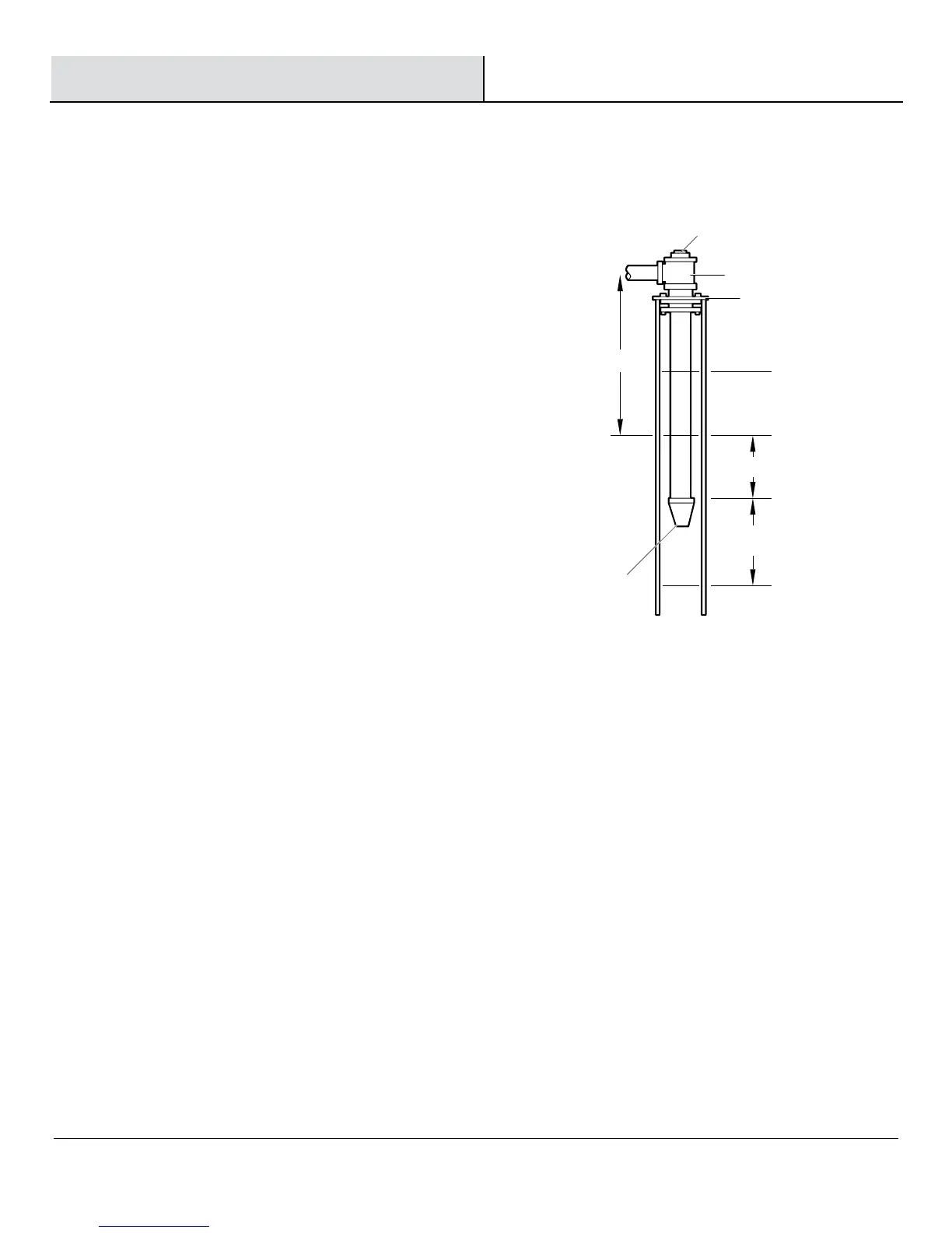
2. If using a foot valve, connect the foot valve and strainer to
the first length of suction pipe and lower the pipe into the
well. Add sections of pipe as needed, using Teflon tape on
the male threads. Use 1-1/2 in. pipe for suction pipe. Be
sure all suction pipe is leak proof or the pump will lose
prime and fail to pump. Install foot valve 10 to 20 ft. (3 to 6
m) below the lowest level to which water will drop while
the pump is operating (pumping water level). Your well
driller can furnish this information.
3. To prevent sand and sediment from entering the pumping
system, a foot valve/strainer should be at least 5 ft. (1.5 m)
above the bottom of the well.
4. When proper depth is reached, install a sanitary well seal
over the pipe and in the well casing. Tighten bolts to the
seal casing.
5. When using a foot valve, a priming tee and plug are
recommended.
Pr
iming plug
Priming tee
2
0 feet (6m) max.
10-20 fe
et (3-6m)
Starting water
level (pump off)
Drawdown water
level (pump on)
Foot
Valve/Strainer
Suction pipe
Well seal
t le
ast 5 feet (1.5m