78
Electrical System
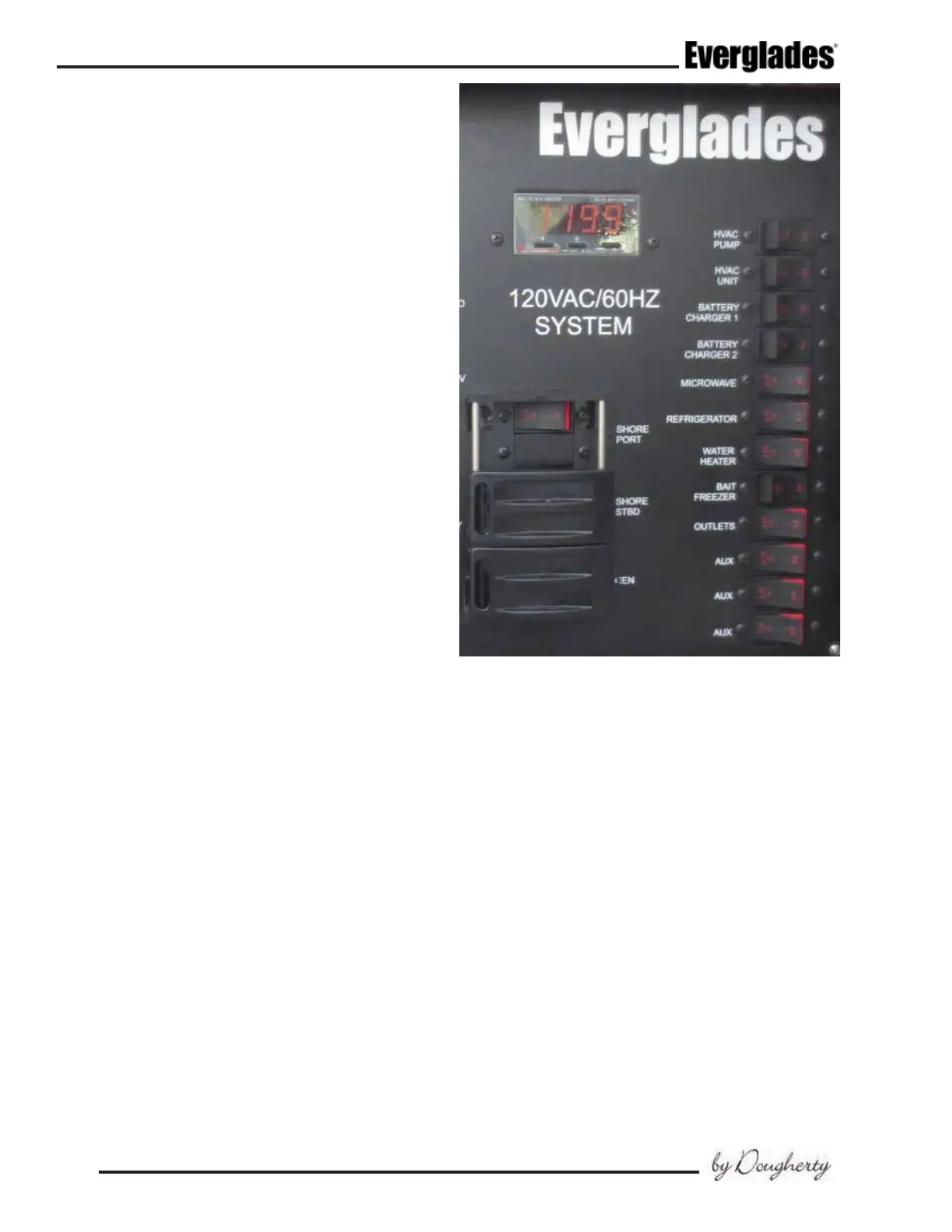
Shore Port/Starboard and Generator Main
Breakers
These breakers select the power source and pro-
tect the general distribution network. There is
a main breaker for each shore inlet connection
circuit and the generator. A sliding safety cover
on the main breakers prevent activating circuits
for the generator and shore circuit or both shore
circuits simultaneously. These breakers are very
sensitive. The resulting power surge that occurs
when connecting the dockside cord may cause the
main breaker to trip. To avoid this surge, always
turn the Shore PWR main breaker to the “OFF”
position before plugging or unplugging the shore
power cord and the Generator main breaker to
the “OFF” position when starting the generator.
Care must be taken when operating the AC system
from the generator or the shore power supply line.
On some boats it may be possible to overload the
generator or shore power circuit if too many AC
accessory breakers are activated. Too much am-
perage being supplied through the panel will cause
the Shore main or Generator main breaker to trip
and could damage the system. This is particularly
important when operating the air conditioner and
water heater. You should always be aware of the
electrical load needed to activate accessories and
manage the amperage being supplied so the load
can be kept within safe limits. If you have any
questions about managing the power in your boat,
contact your authorized Everglades dealer.
HVAC Pump
Supplies electrical current to the seawater pump
in the mechanical systems compartment that
circulates seawater through the air conditioning
units. The pump runs whenever an air condition-
ing unit is operating.
HVAC Unit
Supplies electrical current to the air conditioner
compressor and control panel located in the cabin.
Notice:
After a certain amount of time without water
ow, the air conditioning unit will automati-
cally power down. If this occurs, reset the
unit and check for water ow out of the air
conditioning thru-hull. Refer to the air condi-
tioner owner’s manual for more information.
Battery Charger 1 & 2
Supplies electrical current directly to the automatic
battery chargers located on each side of the electri-
Shore PWR/Generator Main Breakers
cal systems compartment. The battery chargers will
charge and maintain the 12 volt batteries simulta-
neously when activated. They are fully automatic.
The wires that supply DC charging current to the
batteries are protected by an internal fuse in the
battery charger and external fuses, one for each
battery output wire near the batteries. The ex-
ternal fuses protect the DC charging circuit from
the batteries to the charger. The internal fuses in
the charger protect the DC charging circuit from
the charger to the batteries. Refer to the battery
charger owner’s manual for more information on
the features and operation of the battery charger.
The charge to the engine batteries can be moni-
tored by using the volt meters in the engine gauge
cluster or the LED lights on the charger. To monitor
the engine batteries with the volt meters in the en-
gine gauge cluster, activate the chargers and turn
the engine battery switches on. Turn the ignition
switch for each engine to the “ON” position (DO
 Loading...