Topaz Router
Revision 2.0 Page 3
2. INSTALLATION
This section describes how to install the system in the most effective and efficient manner. The system
has been designed with the goal of being simple to install; we trust that you will agree.
2.1. UNPACKING
Remove the equipment carefully from the boxes and check against the Packing List supplied with each
unit. The list identifies what items have been shipped against your order and includes all options. Any
error should be reported to your supplier immediately. After you have unpacked the equipment please
save all the packing material as this could be useful in the future if the unit needs to be returned for
maintenance.
Check each item supplied for transit damage. Any damage should be reported in detail to your supplier.
You must state the serial number of the unit (to be found on the rear or side of each unit). Check that
power cords supplied are suitable for your country and that the equipment is compatible with your
mains (line) voltage. Note that remote panels are mains powered and must also be checked.
2.2. PHYSICAL INSTALLATION
2.2.1. Router Frames
All units are designed for mounting in standard 19" equipment racks. The depth of all the frames is
130mm plus connectors, except the Analog Video, which is 275mm. In addition, allowance must be
made for the high number of cables to be installed at the rear of the frame.
Power dissipation in all units is low and cooling is achieved by natural convection.
2.2.2. Remote Panels
The Q-Link remote panels are 130mm deep plus cables. All remote panels are designed to fit into
standard 19" equipment racks and can be mounted at any angle.
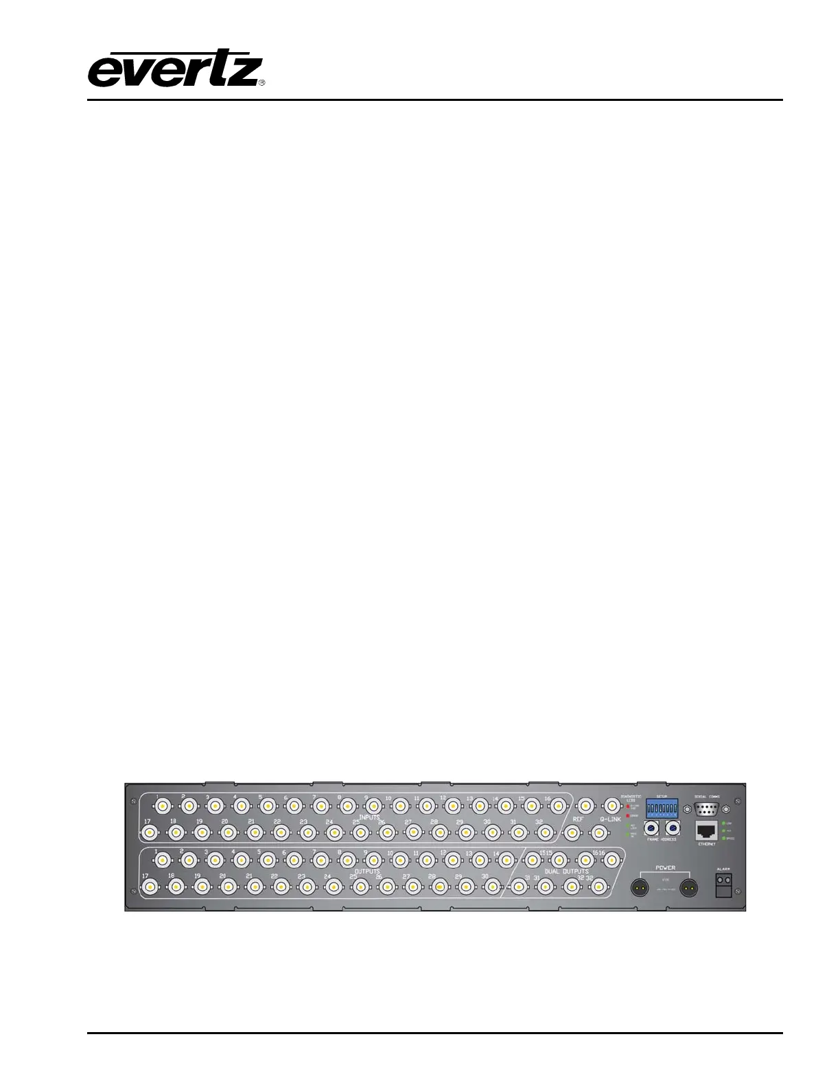
2.3. ELECTRICAL CONNECTIONS
The following images provide a view of the rear panels and the connectors.
Figure 2-1: Rear View of Topaz QT-3232S Router