Topaz Router
Revision 2.0 Page 7
The router has been built to minimize RF emissions. It is important you use tin and dimple D-type
connectors with metal shells connected to the screen of external cables in order to achieve low RF
emissions from this equipment. The shells are fixed by screw locks with 4-40 UNC threads.
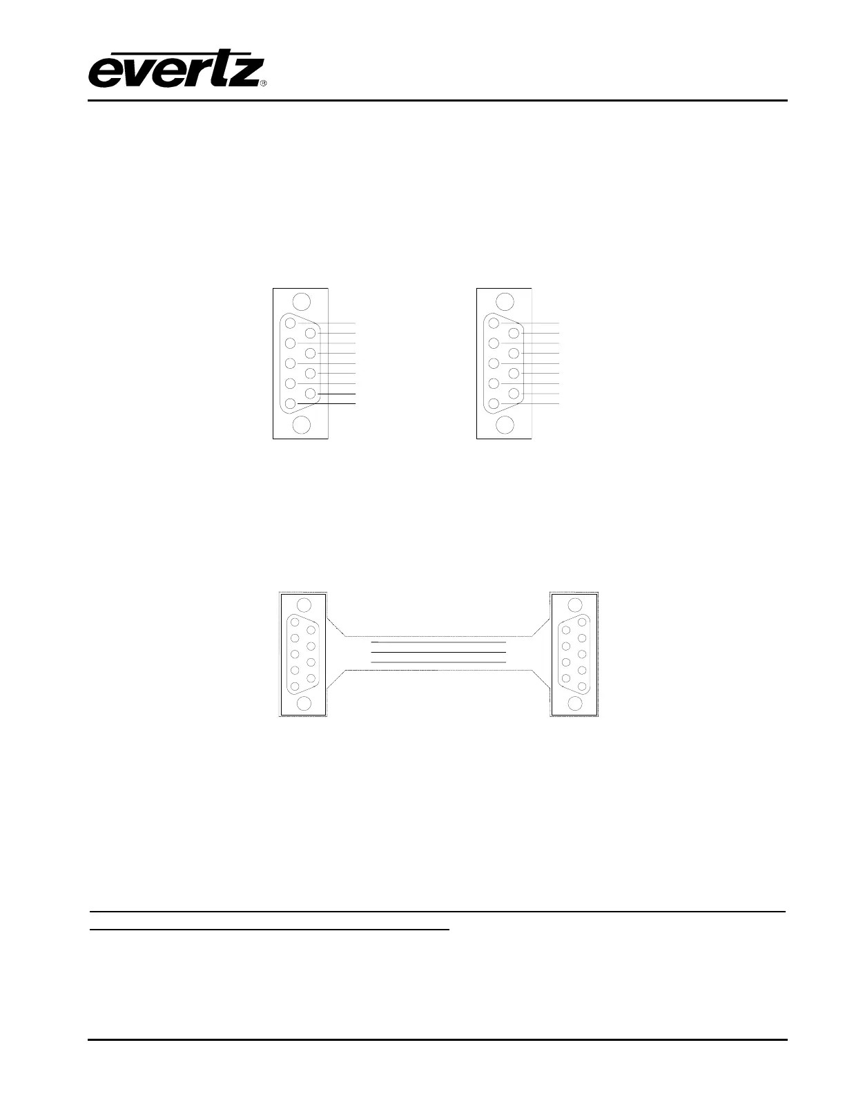
The Computer Interface connector on the equipment is a D-Type 9 socket using the pin connections
shown below. The wiring of the connectors is different for RS232 and RS422. Note that the pin
connections described below only apply to the Topaz units that also provide Ethernet support. Earlier
models of the QT-SD router have the TX+/- and RX+/- signals inverted on the RS422 interface,
otherwise they are the same.
1
2
6
7
3
8
4
9
5
0V
GND
RTS
TXD
RXD
CTS
0V
Not Used
Not Used
1
2
6
7
3
8
4
9
5
TX 0V
GND
TX-
TX+
RX+
RX-
RX 0V
Not Used
Not Used
RS-232
RS-422
Figure 2-10: RS232/422 Connecting to the Router
2.3.7. RS232 PC Interface Cable
The cable between the PC and the router only needs to use TX, RX, and GND as shown below.
The cable between a PC with a D-Type 9 way connector and the router:
1
2
6
7
3
8
4
9
5
TXD
RXD
GND
2
3
5
1
2
6
7
3
8
4
9
5
Cable 9-way to 9-way
RS-232
RXD
TXD
GND
7
3
6
To
Computer
D-9
Socket
To
Router
D-9
Plug
Figure 2-11: RS232/422 Connecting to the Computer
2.4. POWER
The Topaz range uses a common external PSU ‘brick’ that is auto-ranging and converts nominal 115V
or 230V AC mains voltages to safe 12V DC. This then connects to the Topaz router where any
internally required voltages are generated. The external PSU has an IEC inlet and approx 1.7m of DC
lead terminated in a two-pin bayonet style connector.
IEC connectors have an earth pin and as matter of safety this earth pin must be connected to a
solid ground to ensure a proper earth connection.