6.3.3. CODConnectivity in HD
SDI Panels
In a 1st step, the OUT channels are cabled first starting from top to bottom, using only the
first two connectors of the codec modules.
In a 2nd step, the IN channels are cabled starting from bottom to top, using the first two
connectors of each available codec module.
The remaining IN channels can only be cabled on the connectors C and D of the codec
modules on which HD IN channels are already cabled.
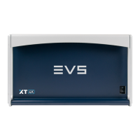
OUT Channels
Connector label HDMode
OUT 1A SDI output of the OUT1 channel.
OUT 1B SDI output of the OUT2 channel.
OUT 1C SDI monitoring output of the OUT1 channel.
OUT 1D SDI monitoring output of the OUT2 channel.
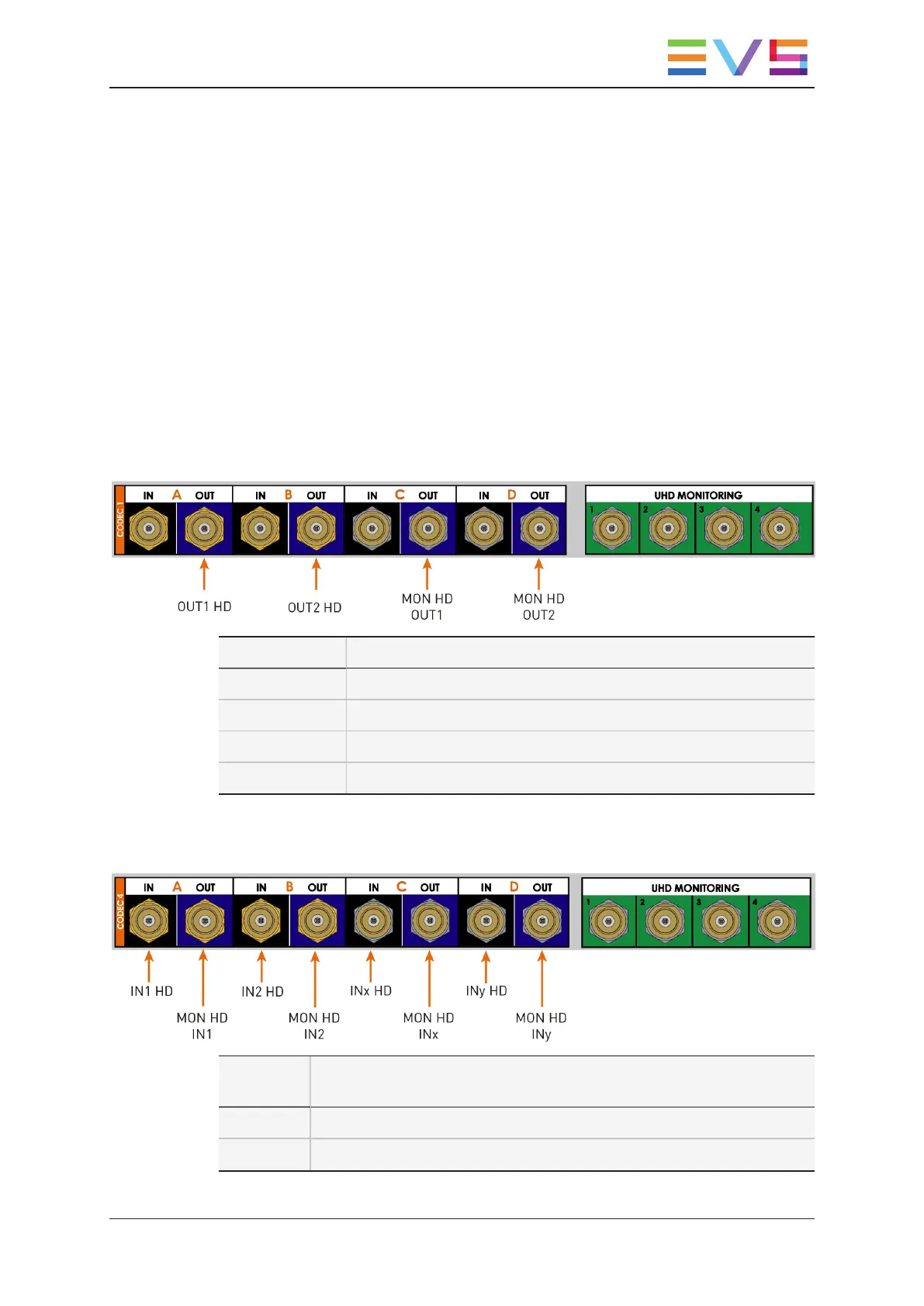
IN Channels
Connector
label
HDMode
IN 4A SDI input of the IN1 channel.
IN 4B SDI input of the IN2 channel.
TECHNICAL REFERENCE MANUAL XT4K Server 15.2
6. Boards Description 65


![Preview: EVS XT[2]](https://data.easymanua.ls/products/617905/200x200/evs-xt-2.webp)


