12
THG/TLG/TLT
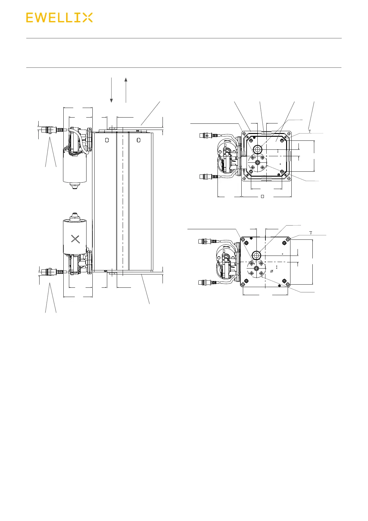
4.2.2 TLT2
Fig. 4
1. Upper attachment plate (optional), see g.3
2. Direction of motion when extending
3. Direction of motion when retracting
4. Transport screws (refer ⮑ chapter 6.4 Installation)
5. Connection cable DIN8
6. Connectioncableminit(optional)
7. Lower attachment plate (optional), see g.3
78
+1
0
163
63,5
+1
0
Ø6
±2
21
±2
29
±2
29
±2
146
±0,2
146
±0,2
this area must be supported
this area must be supported
Ø28
±0,5
Ø28
±0,5
(screw)
78
+1
0
7,5
+1
0
63,5
+1
0
Ø6
±2
Ø28
±0,5
7,5
+1
0
M10 30 (×4)
M10 30 (×4)
21
±2
Ø60
Ø28
±0,5
(screw)
78
+1
0
63,5
+1
0
Ø6
±2
21
±2
29
±2
29
±2
146
±0,2
146
±0,2
101
±0,2
101
±0,2
Ø60
(78)
this area must be supported
this area must be supported
Ø28
±0,5
78
+1
0
7,5
+1
0
63,5
+1
0
Ø6
±2
Ø28
±0,5
7,5
+1
0
M10 30 (×4)
M10 30 (×4)
21
±2
Ø60
Ø28
±0,5
(screw)
163
21
±2
29
±2
101
±0,2
101
±0,2
Ø60
(78)
this area must be supported
this area must be supported
Ø28
±0,5
(screw)
78
+1
0
7,5
+1
0
63,5
+1
0
Ø6
±2
Ø28
±0,5
7,5
+1
0
M10 30 (×4)
M10 30 (×4)
21
±2
Ø60
Ø28
±0,5
(screw)
Top view
Bottom view
8. Lower base plate
9. Outer guide tube
10. Upper base plate
11. Middle guide tube
12. Inner guide tube (not visible)
13. Motors and Encoders (optional)
9
8
5
5
6
6
11
13
13
10
23
412