33
10.0 Dismantling
10.0 Dismantling and disposal
Following the end of its useful life, the appliance must be un-
installed and disposed of in accordance with the local envi-
ronmental regulations.
10.1 Safety
Improper dismantling
WARNING
Danger of injury due to improper dismantling
Stored residual energy, angular components, points and edges
on and in the appliance or on the tools needed to uninstall can
cause injuries.
Therefore:
• Ensurethereissucientspacebeforestartingwork.
• Handle exposed, sharp-edged components with care.
• Pay attention to orderliness and cleanliness in the workplace!
Loosely stacked or scattered components and tools could cause
accidents.
• Uninstall the components properly. Note that some components
may have a high intrinsic weight. Use hoists if necessary.
• Secure components so that they cannot fall down or
topple over.
• Contact the manufacturer if in doubt.
10.2 Dismantling
10.2.1 Dismantling the telescopic pillar
1. Disconnect the device’s control from the power supply.
2. Pull the jack or DIN-8 plug of the telescopic pillar out of
the control unit.
3. Secure elements of the application so that no loads act
on the attachment plates.
4. Loosen and remove the screws for the application/at-
tachment plates of the telescopic pillar or application on
the upper and
lower side of the telescopic column.
5. Disconnect the telescopic pillar from the elements of the
applications.
6. Loosen and remove any attachment screws present for
the attachment plates.
7. Clean the device.
8. Carefully pack the device for shipment to the manufac-
turer (refer to chapter 5.3 Return shipment to the manu-
facturer).
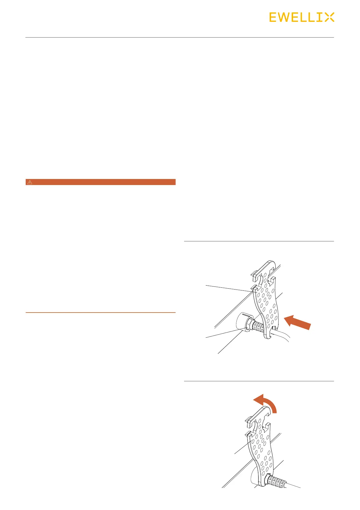
10.2.2 Pull the jack out of the KOM
control unit
Proceed as follows to pull jack out of the connection socket
of the control unit:
• Special tools required:
- Special tool from the manufacturer
(part no. ZBG-140375 (0125322))
1. Insert special tool (1) in the groove (2) of the jack plug.
Fig. 32
Connection, KOM control in this example
2. Turn special key (1) counter-clockwise until the bayonet
joint of the jack plug is unlocked.
Fig. 33
1
1
2