23
6.0 Installation and initial operational set-up
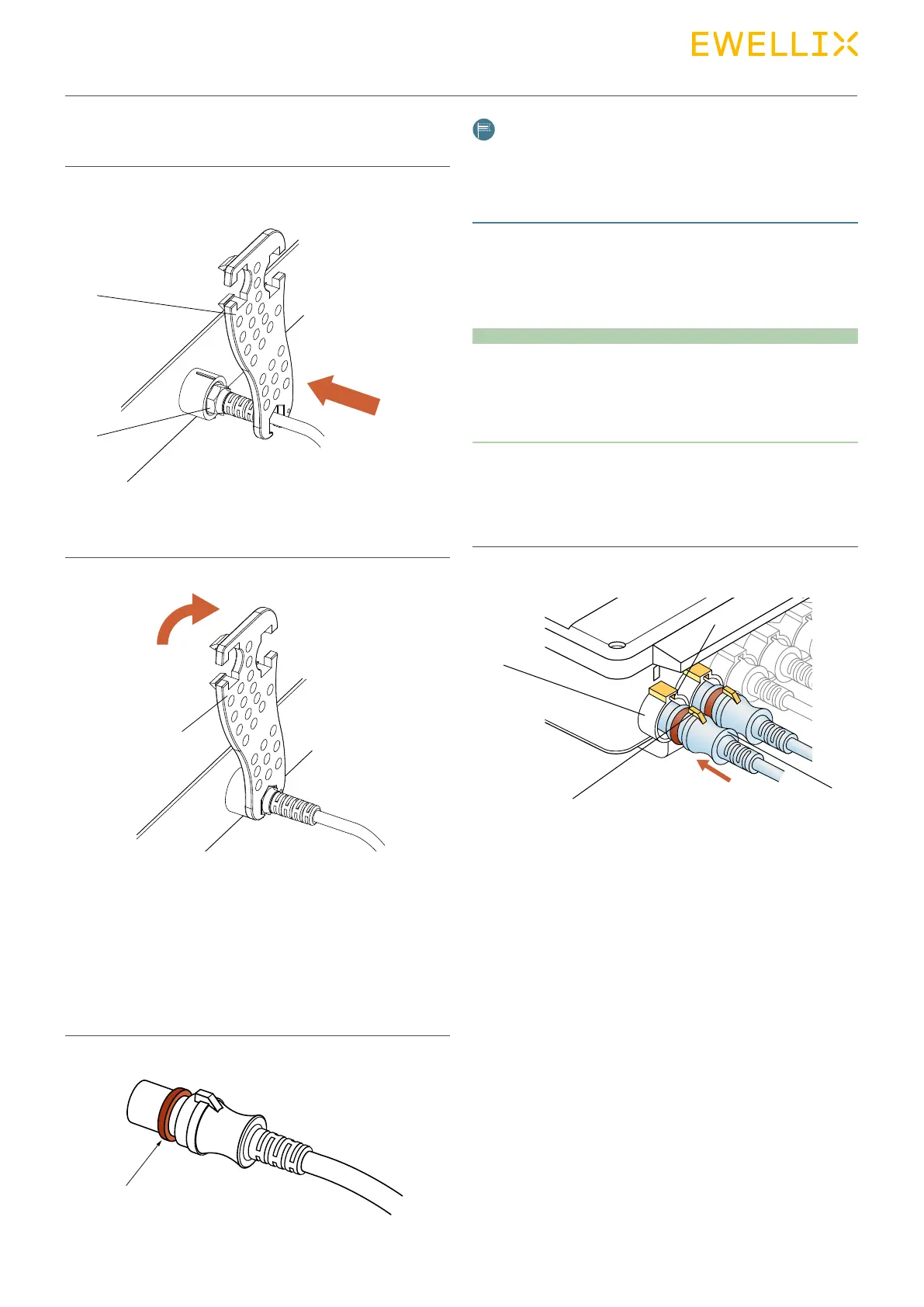
4. Insert special tool (1) in the nut (2) of the jack plug.
Fig. 20
5. Turn special tool (1) clockwise until the bayonet joint of
the jack plug is locked.
Fig. 21
6.5.2 Connect DIN-8 plug to control unit
The insertion position is dictated by the geometric shape of
the plug. The strain relief for this system is provided via at-
tached components of the Ewellix control unit´s casing.
1. Check the sealing ring of the DIN-8 plug (arrow) and the
plug for damage.
Fig. 22
2
1
1
NOTE
Damaged sealing rings and twisted plugs can no longer
provide protection pursuant to IPX6S. They have to be replaced
by the manufacturer (refer to chapter 5.1 Safety information for
the transport).
Connection, BCU control in this example
2. Lightly lubricate sealing ring (arrow) with Klübersynth VR
69-252 (part no. 0118037).
NOTICE
Damage due to wrong lubricants!
The use of incorrect additives may cause significant material
damage.
Therefore:
• Only use the auxiliary products listed by the manufacturer.
3. Insert DIN-8 plug (3) into the connecting socket (1) of the
control unit. Ensure correct positioning of the groove (2)
and the lug (4).
Fig. 23
1
2
4
3