Operation
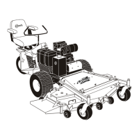
Figure6
1.Decksupportpin
2.CuttingHeight
B.ThetirepressuresaresetasdirectedinCheck
TirePressuresintheMaintenancesection.
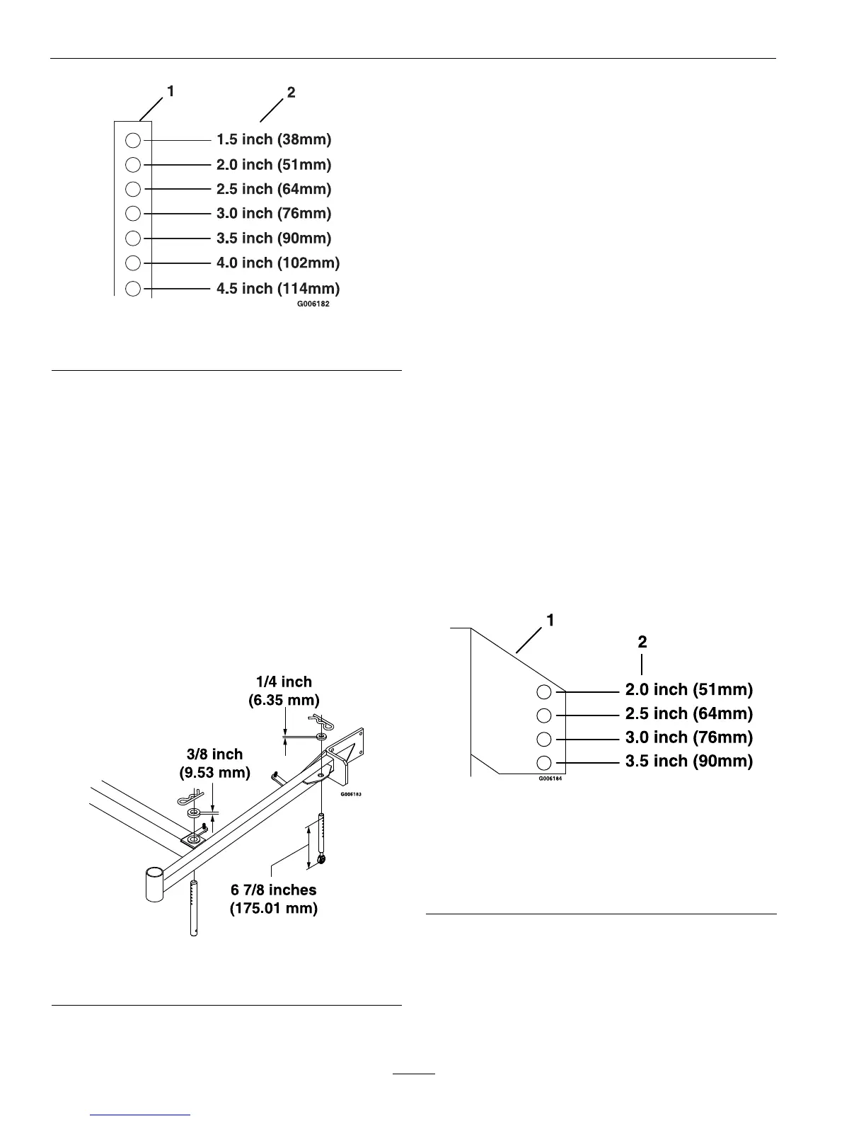
C.Thelengthofthereardecksupportlink
assembliesaverage6.89inches(approximately
67/8inches)(175.01mm)fromthecenterof
theballjointtothecenterofthefarthesthole.
See
Figure7.
Note:Allfourpinsmustequallysupportthe
weightofthedeck.Adjustmentinthelength
ofthereardecksupportassembliesmaybe
necessary.Ifonesideislongerthan6.89
inches(approximately67/8inches)(175.01
mm),thantheoppositesidemustbeshorter
bythesameamount.
Figure7
LeftHandSideShown
AdjustingtheAnti-ScalpRollers
Itisrecommendedtochangetheanti-scalproller
positionwhentheheightofcuthaschanged.
1.Stopthemachineandmovethedriveleversto
theneutrallockposition.
2.DisengagethePTO.
3.Engagetheparkbrake.
4.Stoptheengine,removethekeyandwaitforall
movingpartstostop.
5.Afteradjustingtheheightofcut,adjustthe
anti-scalprollersbyremovingthewhizlocknut
andspringdiscwasher.
6.Adjustanti-scalprollersforNormalOperating
Conditions.Placerollersinoneofthepositions
shownin
Figure8.Rollerswillmaintain3/4
inches(19mm)clearancetothegroundto
minimizegougingandrollerwearordamage.
Note:ForMaximumDeckFlotation,place
rollersoneholepositionlower.Rollersshould
maintain1/4inch(6.35mm)clearancetoground.
DoNotadjustrollerstosupportthedeck.Be
surerollerboltsareinstalledwiththespringdisc
washerbetweenheadofthenutandmounting
bracket.
Figure8
Forcuttingheightsabove3.5inches(38mm)usethe
bottomhole.Therollerswillstillbeeffectiveagainst
scalping.
1.Anti-scalproller
mountingbracket
2.Cuttingheight
7.Torquethe3/8–16whizlocknutto30-35ft-lb
(41-47N-m)(Figure9).
8.Ifthe3/8nylocnuthasbeenremoved,reinstall
andtorqueto30–35ft-lb(41-47N-m)(Figure9).
22
 Loading...