WEAT V2 N - V1
14GB
VR1 VR2 VR3 VR4 VR5
LD1 LD2
BAT 12V
ANT PED STP VAPHO MOT1STR TXF
EXT.LAMP
EL.LOCK LAMP
P1/SFT P2/RADIORESET
MOT2
+
-
JP1
STOP
PHO
VA
TXF
EL S1 S2
MOT 2 MOT 1
ANT
Connection and commissioning of the unit
©h{wz~{]{{wiw|{_yx{|{w}~{{wD
©_wwy~Ew}y~~{wwyyzwy{~y{wzwzD
©fw~{ywx{x{{}{ww{~{{ywx{|~{yywx{D
©Y{y~{{wzyywx{wyyz}~{{{{x{P
The STOP button or switch must be equipped with a manual release. Shunt the button’s terminals on the
board.
Make sure all the inputs on the terminal block are wired correctly and in proper working condition.
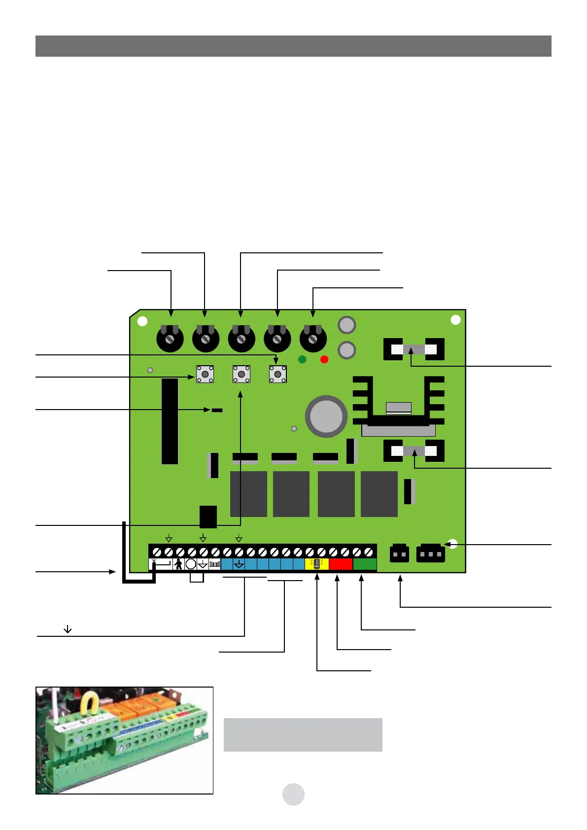
8. CONTROL DEVICE (electronic board)
To facilitate the connection the
terminal boards are removable.
Reaction time to the obstacle
Pause time
Motor force
RESET button
Auto-memorisation
button P1 /SET
Jumper JP1
Removed: remote
control buttons
A or B usable
In place: remote
control buttons C
or D usable
Radio antenna
EL-S1-S2
Lighting module
Motor 2
Battery pack option
WEATBT B2
Backup
transformer
10A fuse,
battery pack
option
Fuse 3 A
«accessories»
Obstacle detection
Motor lag at closing
Auto-memorisation
button
P2/RADIO
PHO- -VA-TXF
Photocells
Beacon
Motor 1
 Loading...