WEAT V2 N - V1
15GB
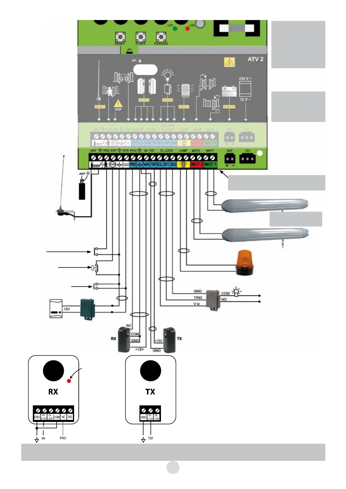
IMPORTANT :
- Jumper JP1 in place:
remote control buttons
C and D usable.
- Jumper JP1 removed:
remote control buttons
A and B usable.
Once the connections
performed, connect the
230 V~ as indicated on
page 10
The terminal boards are removable,
see page 14
SEE DRAWING P 16
12 V flashing beacon
No specific polarity
Control for lighting the gate’s path.
Non-adjustable time delay of 60 sec.
This “lighting system” module must be
obligatorily installed in a CLASS II, IP44
electrical cabinet.
The following occurs if the photocell is activated:
- Movement reverses immediately during closing.
- Closure controls inhibited while gate is open.
Automatic mode is not possible if photocells are not fitted
If the red LED inside the RX portion is lit, the photocells are
aligned.
The set of photocells must be positioned 40 cm from the bot-
tom of a post on the non-opening side of the gate.
230 VAC protected
WEATCR 2
(supplied)
100 W
maxi
neutral
live
Optional antenna
WEATAN 2
(Remove original
wire from terminal block)
Partial opening control
(1 leaf)
Manual control
(button, door phone,
etc.)
Red
Black
Doorphone
or videophone
2 wires
White
White
EMERGENCY STOP (button with
normally closed contact)
Remove the link cable from the
card only if the button is connected
WE 8111 BIS
(supplied)
Important : The installation of the photoelectric cells should be obligatorily finalised with an auto-memorisa-
tion, otherwise the automatic closing function will not be validated.
Do not forget
the shunt between COM
and GND (originally
installed)
Alignment
LED on if
alignment
correct
 Loading...