INSTALLATION
11
ENGLISH
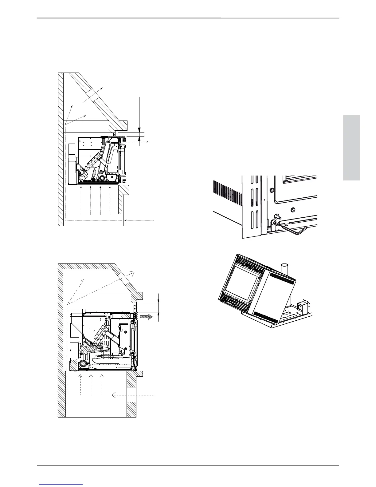
including openings of 600 cm.
The openings in the upper part must be realised above the
upper clearance of the insert.
This ventilation system is totally independent from the air
intake for combustion!
COMFORT MAXI - P80
50 mm
A
B
C
gure 21
COMFORT PLUS - MINI - CRYSTAL
86 mm
A
B
C
gure 22
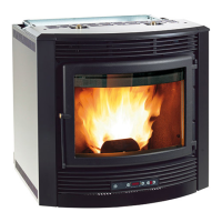
STANDARD ASSEMBLY5.4.
First of all, check the presence of a current socket on the rear of the
insert so that the socket is accessible once installation is completed.
After having evaluated the correct position, the machine body
must be detached in order to x the sliding base: use the supplied
Allen key to turn the lockbolt clockwise (present at the front in
the bottom left or right, depending on the model).
Fix the base using the locking screws.
Connect the conveyor pipe correctly to the piping for evacuation
of combustion products, the air vent box to the relative intake pipe
and in the case of Comfort Plus also the ducting piping.
Re-position the machine body by repeating the operations carried
out previously in the reverse order.
Finally, use the Allen wrench to turn the lockbolt anti-clockwise to
block movement.
To understand whether the insert is correctly attached to the
base, connect the plug to the socket and set the master switch at
position 1: the display should switch on. The lower grate of the
insert must lie at least 1 cm above the re surface in covering
marble.
gure 23
gure 24
FRAMES ASSEMBLY EXCLUDING 5.5.
MODEL P80
Front frame
Side frames
Fix the lateral frames using 2 self-threading screws per side, which
are supplied: the right and left sides are already perforated for xing
the two frames.Any wooden beams situated above the insert
must be protected with re-proof material. Frame assembly
is important as it allows correct recirculation of the air and
consequently optimal product functioning.