The rear panel of the switch includes:
• 3 fan modules
• Grounding lug
• 1 Type-A USB port
• 2 power supply slots
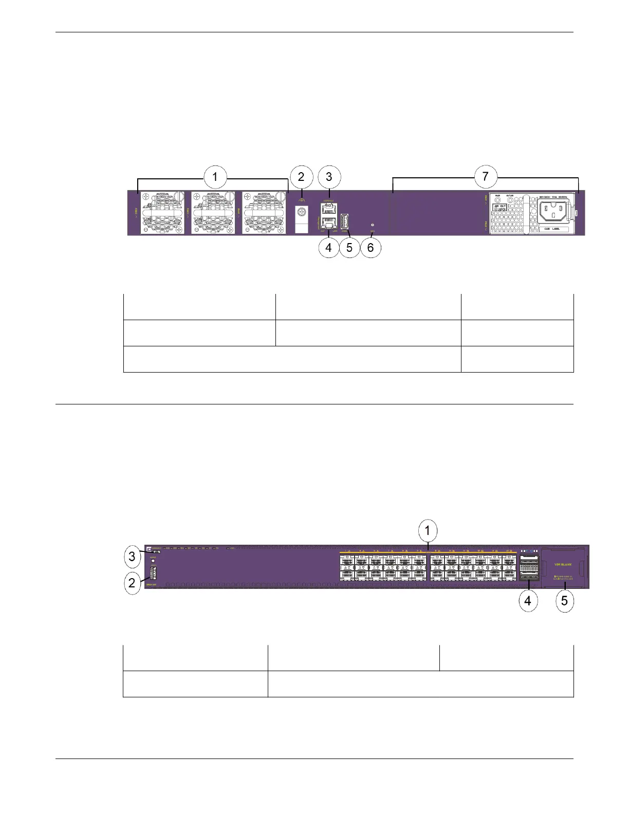
Figure 4: 5520-24W Rear Panel
1 = Fan modules 3 = Serial console port 5 = USB 2 port
2 = Grounding lug 4 = OOB management port 6 = Locator LED
7 = Power supply slots
5520-24X Switch Features
The front panel of the 5520-24X switch includes:
• 24 1GB/10Gb SFP+ ports
• 1 VIM slot
• 1 Type-A USB port
• 1 Micro-B USB console port
• 2 Stacking/QSFP28 ports
Figure 5: 5520-24X Front Panel
1 = 1GB/10Gb SFP+ ports 3 = Micro-B USB console port 5 = VIM port (covered)
2 = USB 1 port 4 = Stacking/QSFP28 ports
5520-24X Switch Features ExtremeSwitching 5520 Series Overview
16 ExtremeSwitching 5520 Series Hardware Installation Guide

 Loading...
