• The power cord must have an appropriately rated and approved wall plug applicable to the country
of installation.
• For cords up to 6 feet (2 m) long, the wire size must be 18 AWG (.75 mm
2
) minimum; over 6 feet, the
minimum wire size is 16 AWG (1.0 mm
2
).
For details about obtaining AC power cords for use in your country, refer to http://
www.extremenetworks.com/product/powercords/.
Console Connector Pinouts
Table 85 describes the pinouts for a DB-9 console plug connector.
Table 85: Pinouts for the DB-9 Console Connector
Function Pin Number Direction
DCD (data carrier detect) 1 In
RXD (receive data) 2 In
TXD (transmit data) 3 Out
DTR (data terminal ready) 4 Out
GND (ground) 5 -
DSR (data set ready) 6 In
RTS (request to send) 7 Out
CTS (clear to send) 8 In
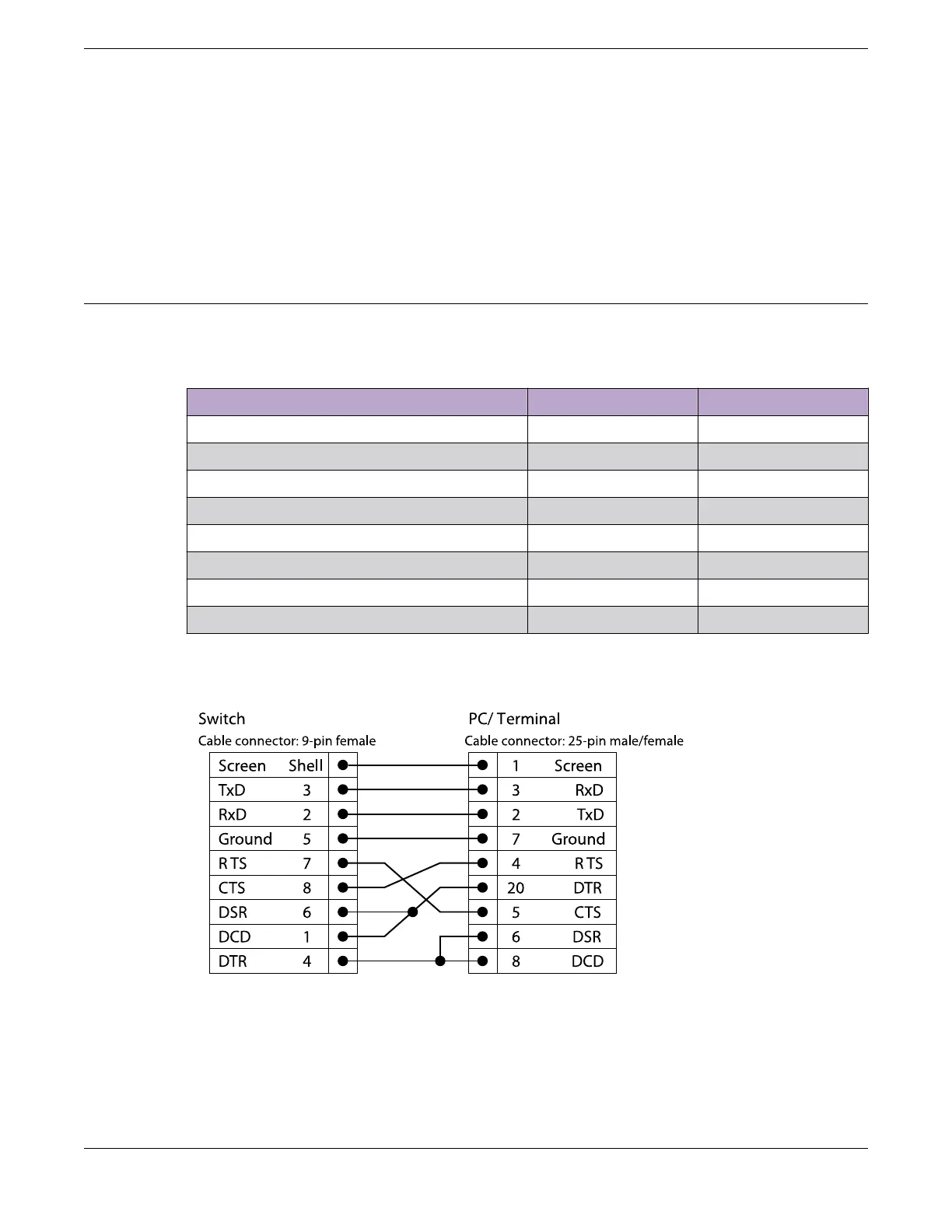
Figure 89 shows the pinouts for a 9-pin to 25-pin (RS-232) null-modem cable.
Figure 89: Null-Modem Cable Pinouts
Figure 90 shows the pinouts for a 9-pin to 9-pin (PC-AT) null-modem serial cable.
Technical
Specifications Console Connector Pinouts
ExtremeSwitching 5520 Series Hardware Installation Guide 147

 Loading...
