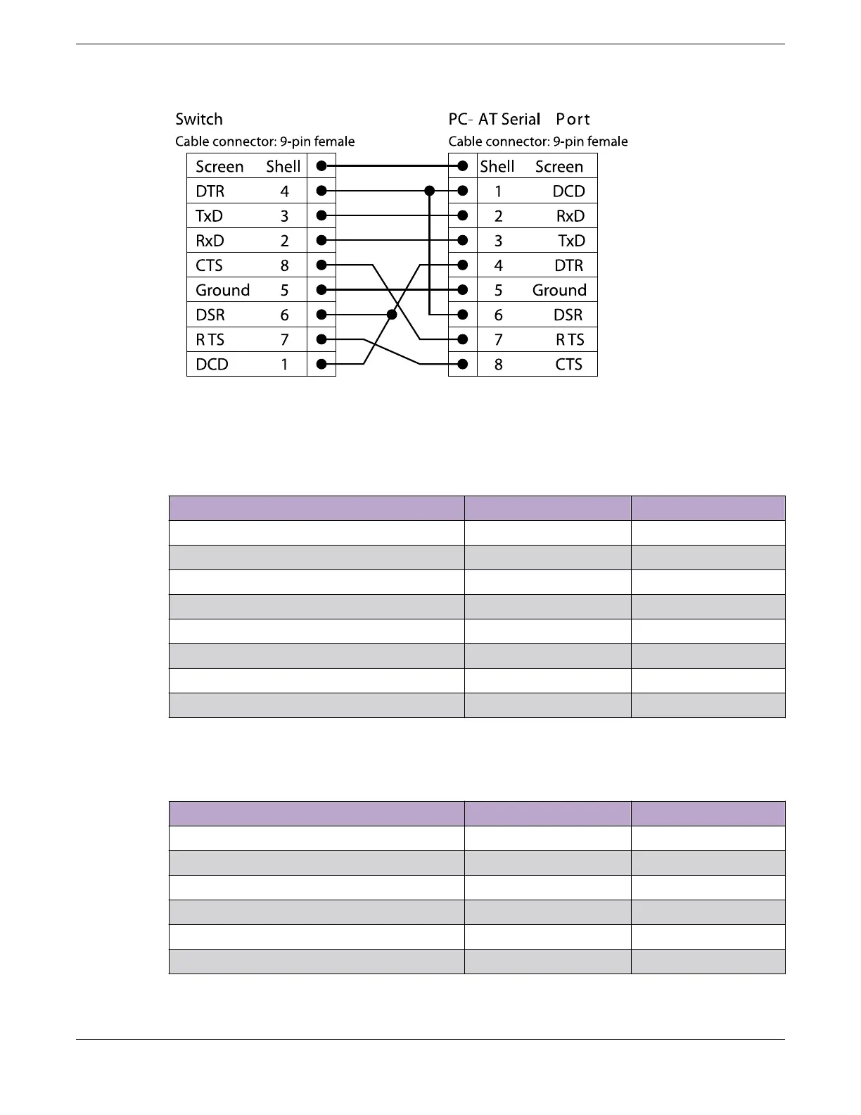
Figure 90: PC-AT Serial Null-modem Cable Pinouts
Table 86 shows the pinouts for the RJ45 console port on the ExtremeSwitching switches.
Table 86: RJ45 Console Port on Switch
Function Pin Number Direction
RTS (request to send) 1 Out
DTR (data carrier detect) 2 Out
TXD (transmit data) 3 Out
GND (ground) 4 —
GND (ground) 5 —
RXD (receive data) 6 In
DSR (data set ready) 7 In
CTS (clear to send) 8 In
Table 87 shows the pinouts for an RJ45-to-DB-9 adapter.
Table 87: Pinouts for an RJ45 to DB-9 Adapter
Signal RJ45 Pin DB-9 Pin
CTS (clear to send) 1 8
DTR (data carrier detect) 2 6
TXD (transmit data) 3 2
GND (ground) 4 5
GND (ground) 5 5
RXD (receive data) 6 3
Console Connector Pinouts Technical Specifications
148 ExtremeSwitching 5520 Series Hardware Installation Guide

 Loading...
