Extron • Matrix 100 • User’s Manual
Chapter 4 - Hardware Installation
IEC Power Panel ............................................................................................................ 4-1
Standard Power Supply..................................................................................... 4-1
Redundant Power Supply (optional) .................................................................. 4-1
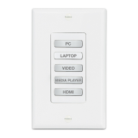
QuickSwitch Front Panel Controller ................................................................... 4-1
Removing the Matrix 100 Cover..................................................................................... 4-2
Changing Matrix Front Panels ........................................................................................ 4-2
Replacing a Blank Panel with a QuickSwitch Front Panel Controller ................. 4-3
Replacing the Lithium Battery ........................................................................................ 4-3
Changing the Main Fuse ................................................................................................ 4-4
RS-232/RS-422 Communications .................................................................................. 4-4
9-Pin Communication Connector ...................................................................... 4-4
RS-232 Protocol................................................................................................ 4-4
Installing a Redundant Power Supply............................................................................. 4-5
Adding an Audio Module ................................................................................................ 4-6
Installing I/O Modules in the Rear Panel ........................................................................ 4-9
Installing QS-FPC Software Update........................................................................... 4-11
Illustrations:
Figure 4-1. IEC Power Panel: Power Switch, Fuse and Power Connectors .................... 4-1
Figure 4-2. Matrix 100 Cover has six screws ................................................................. 4-2
Figure 4-3. Front Panel Cable Connections and Battery Location .................................. 4-3
Figure 4-4. Matrix 100, Face-up ..................................................................................... 4-3
Figure 4-5. Wiring the RJ45 Cable ................................................................................. 4-3
Figure 4-6. Changing the Fuse ...................................................................................... 4-4
Figure 4-7. Swapping the RS-232/RS-422 Port cable .................................................... 4-4
Figure 4-8. Matrix 100 Comm Connector ....................................................................... 4-4
Figure 4-9. Connecting the Redundant Power Supply and Ground Wire
Connections (Right detail) ............................................................................ 4-5
Figure 4-10. Redundant Power Supply Connector ......................................................... 4-5
Figure 4-11. How the Audio Module fits in the Matrix ..................................................... 4-6
Figure 4-12. Audio Module connections and hardware .................................................. 4-6
Figure 4-13. The Matrix Audio Module before installation............................................... 4-7
Figure 4-14. Lift the Back Panel slightly and slip the Audio Module under it ................... 4-7
Figure 4-15. Secure the module in position .................................................................... 4-7
Figure 4-16. Plug the Ribbon Cables from each module to the Main Controller board ... 4-8
Figure 4-17. This illustration shows the modules already installed ................................. 4-9
Figure 4-18. Squeeze the tabs to release the plug ......................................................... 4-9
Figure 4-19. Module differences................................................................................... 4-10
Figure 4-20. DIP Switch operation ............................................................................... 4-10
Figure 4-21. DIP Switch settings for each module........................................................ 4-10
Figure 4-22. MRAM Module ......................................................................................... 4-10
Figure 4-23. Remove the Front Panel to access the Software IC Chip ......................... 4-11
Figure 4-24. Use the PLCC Chip Puller to remove the Software IC Chip ..................... 4-11
Chapter 5 - Windows® Control Software
Extron Matrix Control Software ...................................................................................... 5-1
Windows Example ......................................................................................................... 5-1
Matrix 100/200 Help....................................................................................................... 5-3
Illustrations:
Figure 5-1. Extron Windows Group Example ................................................................. 5-1
Figure 5-2. Control Program Example............................................................................ 5-2
Figure 5-3. Configured Matrix Example.......................................................................... 5-2
Figure 5-4. Example of the Help Menu........................................................................... 5-3
ii
Contents