Network Button Panels • Hardware Features and Installation 19
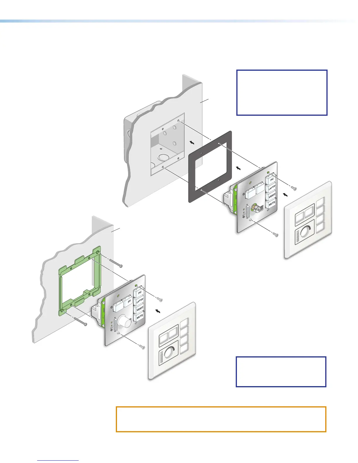
For US gang models (NBP100 and NBP200): Insert the included screws through
the mounting holes at the top and bottom of the unit, through the plastic spacer (if not
using a mud ring), and into the corresponding threaded holes in the box or mud ring
(see figure 19 and figure 20).
RESET
e
ON
PC
VIDEO
MUTE
LAPTOP
OFF
MAC: 00-05-A6-XX-XX-XX
S/N: ####### E######
00-05-A6-XX-XX-XX
Extron
Wall
NBP 100
Mud Ring
Faceplate
b. Using a Phillips screwdriver, lightly tighten the mounting screws until snug.
ATTENTION:
• Do not overtighten the screws.
• Veillez à ne pas trop serrer les vis.
NOTE: If the unit is not installed
in a mud ring, you must install
the plastic spacer. The spacer
positions the unit to allow the
magnetic faceplate to attach
properly and securely.
RESET
e
ON
PC
VIDEO
MUTE
LAPTOP
OFF
MAC: 00-05-A6-XX-XX-XX
S/N: ####### E######
00-05-A6-XX-XX-XX
Extron
Wall
Faceplate
NBP 100
Plastic Spacer
Wall Box
Figure 19. Installing the NBP
in a Junction Box
Figure 20. Installing the NBP
in a Mud Ring
NOTE: Extron recommends
taking precautions to avoid
electrostatic discharge issues
during installation.