Page 19 of 77
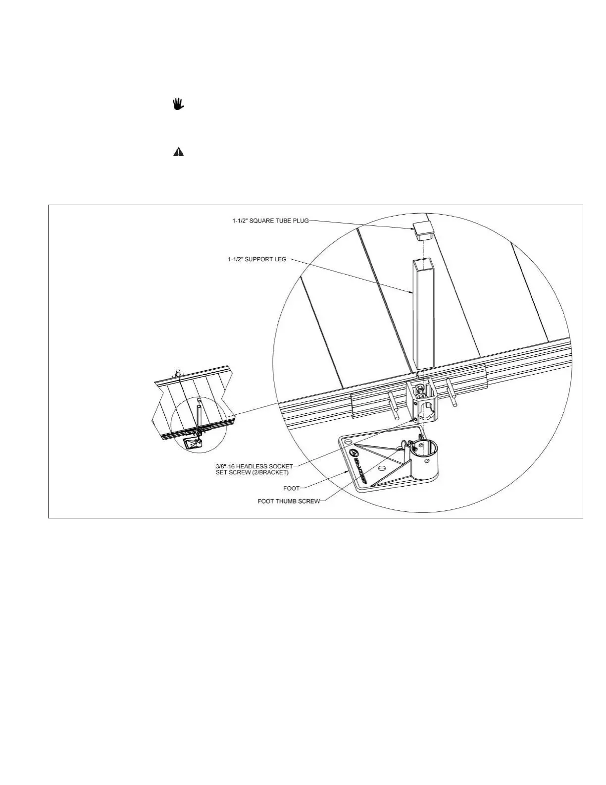
3.3.4. Locate the appropriate TSLxxPR SUPPORT LEG PAIR (where “xx” denotes the leg length)
for the location. Place a foot under the support leg bracket with the foot extending under
the ramp, then insert a 1-1/2” support leg through the support leg bracket into the foot.
Loosen the 3/8”-16 headless socket setscrews and the foot’s thumb screw if needed to
fully engage the support leg in the foot (FIG. 3.7).
If installing on soft soil it may be necessary to set the foot on a concrete pad.
3.3.5. After the support leg is fully engaged in the foot, tighten the 3/8”-16 headless socket
setscrews to 15 ft.-lbs. (FIG. 3.7).
Do not attempt to walk on the ramps until all support leg set screws have been
tightened as specified.
3.3.6. Tighten the foot’s thumb screw and insert 1-1/2” square plug into the top of support leg.
 Loading...