Page 20 of 77
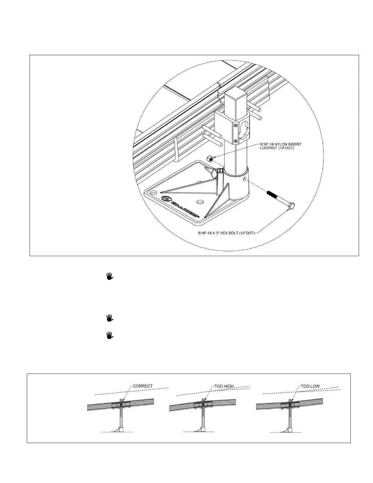
3.3.7. Use hole in the foot as a template to drill an 11/32” or 3/8” hole through each support
leg (FIG 3.8).
3.3.8. Install a 5/16”-18 x 3” long hex bolt through the support leg and foot, then secure with
the 5/16”-18 nylon insert locknut.
3.3.9. Adjust the ramp support legs one at a time.
Building codes and ADA guidelines call for a maximum slope of 1:12 (approximately
5°) and this is the required slope for the TITAN system.
3.3.9.1. Raise (or lower) the ramp sections at the center saddle bracket to take any
sag out of the ramp run, then retighten the two set screws in each support
leg bracket to 15 ft.-lbs. as specified.
Adjusting sections can be accomplished by having someone sight down the ramp
while another person adjusts the ramp height.
It’s important to ensure that the ramp sections are parallel to each other. If they
are not, it may be difficult to install the handrails (FIG. 3.9).
3.3.10. Ensure that all bolts and set screws are tight and the ramp sections are aligned parallel,
on the same plane, to one another.
 Loading...