FX16 Master Controller Technical Bulletin
18
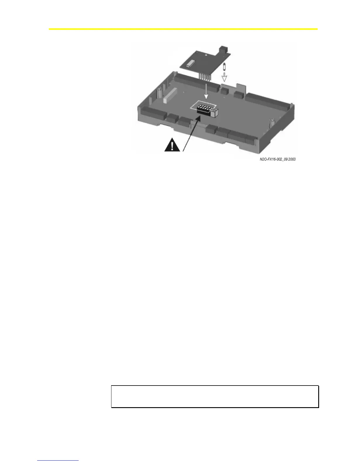
Figure 11: Insertion of the N2 Open Card
5. On the upper DIP switch block (S2), set Switch 1:
Models with an integral display:
0 = baud rate and N2 Address set on DIP switches
1 (On) = baud rate and N2 Address set on controller display
Models without an integral display:
0 = baud rate and N2 Address set on DIP switches
6. If Switch 1 of S2 is set to 0, set the Baud Rate.
Note: For N2 communication with Metasys® supervisory systems,
you must select the baud rate of 9600 (factory default).
7. If Switch 1 of S2 is set to 0, set the N2 Address on the lower DIP
switch block (S1) in binary format (1 = ON). Examples are:
8 7 6 5 4 3 2 1
0 0 0 0 0 0 0 1 = N2 Address 1
0 0 0 0 0 0 1 1 = N2 Address 3
1 0 0 0 0 0 0 1 = N2 Address 129
1 1 1 1 1 1 1 1 = N2 Address 255
Note: Address zero is not supported on the N2 Open network. The
factory default address is 1.
8. Replace the control cover and secure the cover with the two screws.
9. Turn on the controller after you safely restore all connections.
IMPORTANT: If you change the N2 Address during a bench test with power
applied to the controller, cycle the power for a new address to become active
in the controller.
Align the pins as shown in figure