FX16 Master Controller Technical Bulletin 27
Consider the following information when you work with the
connections details for the GSM modem cable:
• Run the modem cable separately from line voltage/power cables and
use a minimum of 30 cm (12 in.) separation for 230 V/30 A circuits.
• Do not run modem cable parallel to power cables for long distances
(> 3m [10 ft]).
• Do not run modem cable close to transformers or high frequency
generating equipment.
GSM Modem Antenna
Connect the GSM modem to a proper antenna with the characteristics in
Table 4.
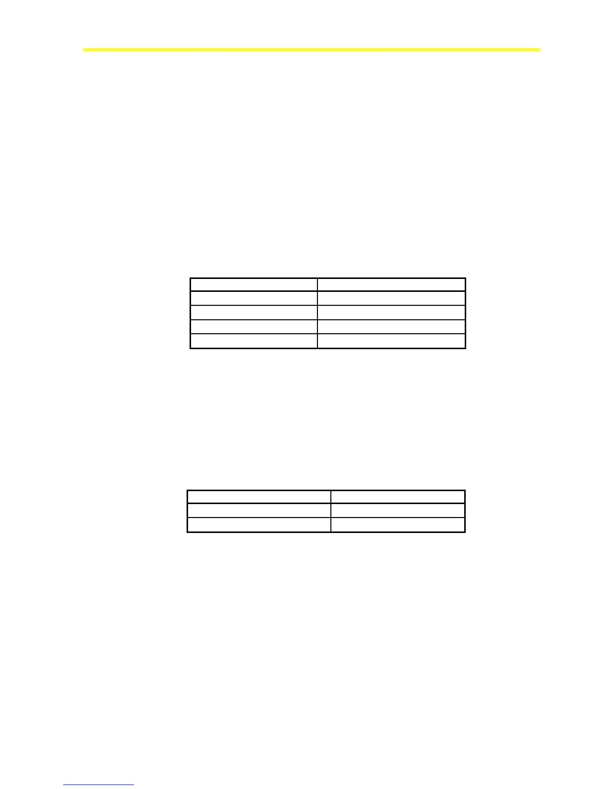
Table 4: GSM Modem Characteristics
Characteristic Description
Frequency range
Dual-band GSM 900/1800 MHz
Impedance
50 ohms
Gain (antenna + cable)
0 dB
VSWR (antenna + cable)
-10 dB
You must install the antenna in a position where the GSM modem field
is strong enough to ensure proper communication.
To verify the GSM signal strength, connect the modem using a null
modem cable to a computer with a VT100 emulator program. Send the
AT command AT + CSQ to the modem. Monitor the response. See
Table 5.
Table 5: GSM Signal Strength
AT+CSQ Response (RSSI) Signal Quality
11 to 31
Sufficient
0 to 10 and +99
Insufficient