Do you have a question about the Fagor Advance and is the answer not in the manual?
Provides essential initial information and precautions for using the appliance safely.
Highlights critical warnings and safety measures to prevent damage or injury.
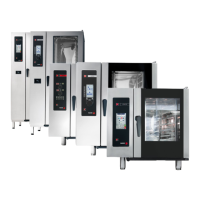
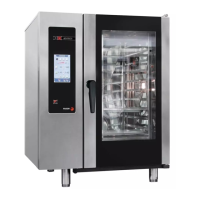
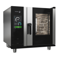
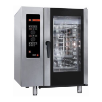
Explains how to interpret the nomenclature for the Advance Concept oven models.
Details the nomenclature for the Advance Plus oven models.
Specifies required clearances around the oven for safe installation and operation.
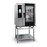
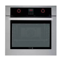
Guides the installation process for table top oven models.
Details mandatory requirements for safe and compliant electrical connections.
Highlights crucial steps before and during electrical connection procedures.
Details maximum gas consumption for various models and gas types.
Provides important remarks, warnings, and ventilation guidelines for gas installation.
Lists gas categories and operating pressures by country for appliance compatibility.
Describes the installation of a gas oven under an extractor hood.
Details the installation of a gas oven below a ventilation ceiling.
Explains how to connect a gas oven directly to a fluepipe.
Specifies water pressure, quality, and connection details for the appliance.
Suggests appropriate filters based on water quality for optimal performance.
Details the installation of the waste water drainage system and its requirements.
Lists the components included in the Advance Drainage Kit.
Illustrates the assembly configuration for Advance Plus ovens.
Shows the assembly configuration for Advance Concept ovens.
Provides detailed diagrams of oven dimensions and connection points.
Shows detailed dimensions and connection points for ACG/AG/APG 101 models.
Presents dimensional data and connection points for ACG/AG/APG 201 models.
Details dimensions and connection points for ACG/AG/APG 102 models.
Shows dimensional data and connection points for ACG/AG/APG 202 models.
Details dimensions and connection points for ACE/AE/APE 061 models.
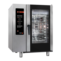
Shows dimensional data and connection points for ACE/AE/APE 101 models.
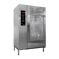
Presents dimensional data and connection points for ACE/AE/APE 201 models.
Details dimensions and connection points for ACE/AE/APE 102 models.
Shows dimensional data and connection points for ACE/AE/APE 202 models.
Step-by-step guide for performing manual cleaning of the oven.
Crucial advice on cleaning products, methods, and safety precautions.
Recommends proper disposal of the product at the end of its useful life for recycling.
Fields for installer details and confirmation of installation compliance.
Advises establishing a regular preventive maintenance program for the appliance.
Checklist for verifying correct installation of the oven and its environment.
Checks related to voltage, consumption, and electrical protections during installation.
Checklist for verifying correct hydraulic connections and water supply.
Checklist for verifying gas supply, type, and combustion parameters.
Comprehensive checklist for testing oven operation and customer instructions.
Illustrates the Fagor drainage kit components and configurations.
Instructions for assembling the base structure of the stacking unit.
Steps for positioning and securing the oven onto the stacking structure.
Instructions for mounting the front panel with seals onto the structure.
Guidance on securing the stacking fluepipe and related cautions.
Steps for preparing the top oven, including leg replacement.
Instructions for mounting the side panel with seals.
Steps for fitting the side panels onto the stacking unit.
Instructions for securing the fluepipe guide and connecting outlets to hoses.
Diagram showing Viewer and Control electronic card arrangements and communication.
Table detailing components for different oven models (e.g., serigraphy, display, control cards).
Illustrates the control panel layout and labels for Advance Concept ovens.
Shows the control panel layout and labels for Advance ovens.
Details the ACE/ACG 12V Display card, its functions, and reference number.
Describes the AE/AG 12V Display card, its features, and reference number.
Details the specifications of the Advance Plus platform including power supply and ports.
Explains the purpose of the BMF communication cable for inter-card communication.
Lists the functions, inputs, and outputs of the Chamber Card Control.
Provides dimensional information and the reference number for the Chamber Card.
Details the functions and outputs of the Boiler Card Control, including pump and dispenser outputs.
Presents dimensional data and reference number for the Boiler Card Control.
Lists the functions and outputs of the Gas Card Control, including blower and gas valve inputs.
Details the specifications of the AC transformer used in the ovens.
Describes the frequency variator used for the chamber turbine motor.
Provides the electrical circuit diagram for ACE oven models.
Presents the electrical circuit diagram for AE oven models.
Illustrates the electrical circuit diagram for COE oven models.
Provides the gas circuit diagram for ACG oven models.
Presents the gas circuit diagram for AG oven models.
Illustrates the gas circuit diagram for COG oven models.
Details motor and turbine part numbers and types for 061 ovens.
Describes motors and turbines for 101-102 oven models, noting turbine size difference.
Details motors and turbines for 201-202 oven models.
Illustrates the assembly of turbine fastenings for the oven chamber.
Shows the internal fastening components for the oven chamber.
Details the assembly of the chamber light components.
Describes different temperature probe types and their installation distances.
Shows the location of the steam generator temperature probe.
Provides assembly distances for the steam temperature probe by model.
Explains the use and specifications of the multi-tip core probe.
Details the Chamber Safety Thermostat, its SAP code and disconnection temperature.
Describes the Steam Generator Safety Thermostat, its SAP code and disconnection temperature.
Lists electric resistors used for convection heating across oven families.
Shows resistor sizes for specific oven models (061, 101, 102).
Indicates heat exchangers used for gas ovens by model family.
Shows the heat exchanger for the ACG/AG/APG 061 oven with SAP code.
Details the heat exchanger for ACG/AG/APG 101 ovens with SAP code.
Shows the heat exchanger for ACG/AG/APG 102 ovens with SAP code.
Details heat exchangers for ACG/AG/APG 201 models, noting burner differences.
Shows heat exchangers for ACG/AG/APG 202 models, noting burner differences.
Lists and illustrates the main components of the convection gas burner.
Explains ignition control variations based on the number of burners.
Details the gas pathway and the mixture process for combustion.
Specifies critical distance checks for burner ignition components.
Lists powers and SAP references for convection and steam burners.
Describes the two types of blowers used and their specifications.
Explains the mixer's function and the need for a specific Venturi washer.
Table detailing Venturi washer types, colors, and SAP codes for different models.
Information on the high frequency spark generator and its control.
Lists principal characteristics and features of the SIT 579 DBC ignition control.
Shows the electrical diagram for the ignition control unit.
Details the characteristics of the SIT gas valve, including electrical connections.
Explains how to measure input and output pressures for the gas valve.
Lists steam generator capacities in litres for different oven models.
Describes a new steam generator design and the common level bottle element.
Details resistors, SAP codes, and power for electric steam generators by model.
Describes the previous atmospheric burner system for steam generation.
Explains the new direct gas burner system for steam generation.
Lists burner SAP codes based on steam generator volume/size.
Outlines the steps required for converting ovens to different gas types.
Provides ignition speed, injector size, and references for 061 model gas conversion.
Details gas conversion parameters for 101 models.
Lists gas conversion specifications for 102 models.
Provides gas conversion parameters for 201 models.
Lists gas conversion specifications for 202 models.
Table identifying solenoid valves, their SAP codes, colors, and applications.
Warns about descaling procedures and explains lime scale detection.
Provides a detailed step-by-step procedure for descaling the oven.
Explains the electrical conversion process from 400V to 230V with diagrams.
Details improvements in door upper and lower fastenings.
Shows adjustment points for door misalignment and seal closure.
Illustrates door components for 201-202 oven models.
Shows positions of fluepipe components like motor and micro switches.
Illustrates the installation and differing positions of the retractable shower.
Explains the sequence of operations during the wash process.
Describes how to abort or complete the wash cycle and its outcomes.
Lists the main components that make up the wash system.
Presents a detailed schematic of the oven's main electrical circuits.
Checklist for regular maintenance and inspection of electric ovens.
Checklist for regular maintenance and inspection of gas ovens.
An empty section for general notes.