Drive modules
DRIVE MODULES
Modular drives
3.
129
DDS
HARDWARE
Ref.1310
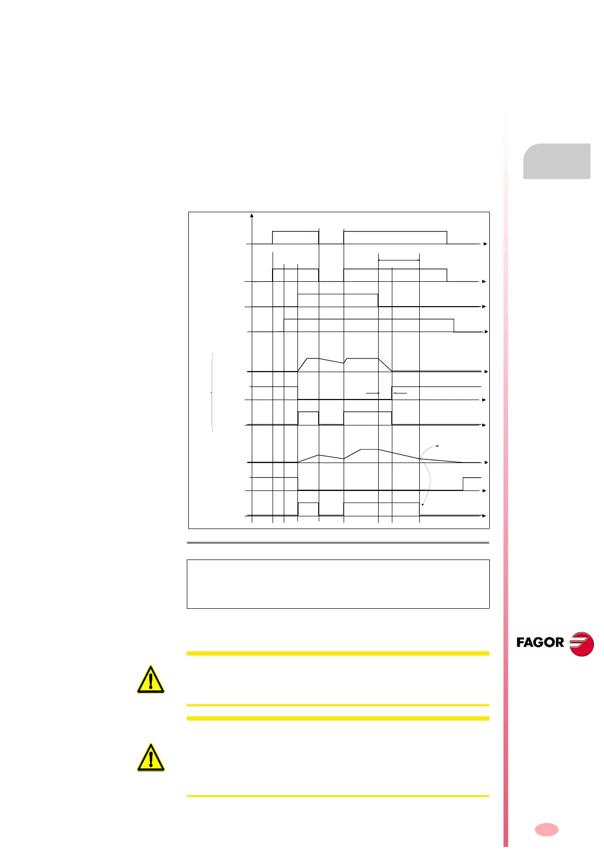
Deactivation of the Speed Enable input
When the Speed Enable input is set to 0 V DC, the internal velocity com-
mand follows the stop ramp set by parameter and:
Situation 1
The torque is kept active by braking the motor. When it stops, variable
SV5 (S00331) is activated. The motor has stopped in a time period
shorter than the one indicated by parameter GP3 (F00702). The
torque is canceled and the rotor is free.
Situation 2
The torque is kept active by braking the motor. When it stops, variable
SV5 (S00331) is activated. The motor does not stop in a time period
set by parameter GP3 (F00702). The motor stops when its kinetic en-
ergy runs out.
See also the internal parameter GP3 (F00702) and the internal variable
SV5 (S00331) in chapter 13 of the “man_dds_soft.pdf” manual that is sup-
plied with this one.
F. H3/61
Operating modes of functions Drive Enable and Speed Enable.
NOTE. Also see in chapter 2 (X2 connector, pin 5 on PS power
supplies), (X2 connector, pin 5 on XPS power supplies) or (X6 connec-
tor, pin 5 on RPS power supplies) corresponding to the System Speed
Enable input and its effect on the Speed Enable inputs of modular drives.
Drive Enable
Signal
Speed Enable
Function
Velocity
command
time
GP3
Trigger Error-4
Braking time < GP3
Proper braking < GP3
Braking time > GP3
SV5:
nfeedback<nmin
TV100:
ParActivo
TorqueState
Case 1: Running normally
-Fast motor response-
Real
Speed
SV5:
nfeedback<nmin
TV100:
TorqueStatus
Case 2: Running improperly
-slow motor response-
Real
Speed
W
i
t
h
t
o
r
q
u
e
N
o
t
o
r
q
u
e
N
o
t
o
r
q
u
e
time
time
time
N
o
t
o
r
q
u
e
time
time
time
time
time
AS1-AS2
time
open contact open contact
close contact close contact
close contact
WARNING. AXD/SPD drives (see DECLARATION OF CONFORMITY
section) have the Drive Enable input as one channel of STO (Safe Torque
OFF) safety function (PL d or SIL 2). Main contactor - KM1 may be used for
another channel. See chapter 9. FUNCTIONAL SAFETY in this manual.
WARNING. In case of mains failure, the control circuit and its signals must
maintain their 24 V DC while the motors are braking.
On modular drives, the 24 V DC needed to activate the Drive Enable must
be obtained from a power supply that maintains its rated value during that
period of time. The PS-25B4 power supply, the APS-24 auxiliary power sup-
ply and the regenerative XPS and RPS power supplies meet this condition.