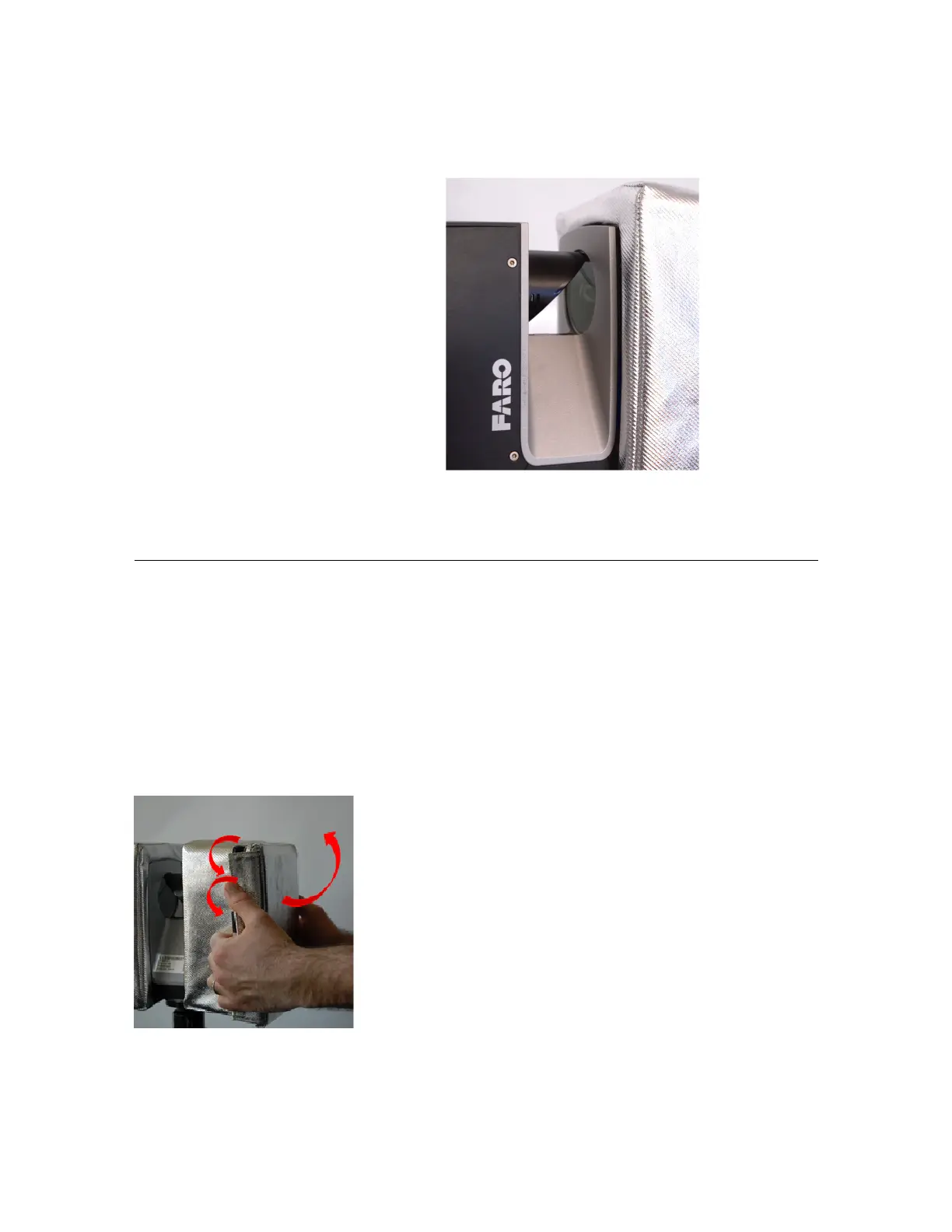
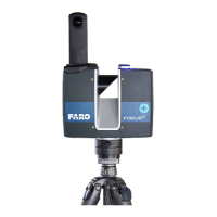
5.Afterinstallation,recheckthepositionof
thecover.Ensurethattheinnerrimlineof
thecoverisalignedparalleltotheinner
edgeofthescannerchassis,withanoffset
of3to4mm.Thescannerchassisshould
bevisiblefromallsides.
Figure 3-7 : Case fixed correctly
Afterinstallingboththecovers,thelaserscannerisnowreadyforoperation.
Accessingthelaserscannerwiththethermalprotectioncoverinstalled
AslongastheFAROLaserScannerisexposedtohotclimateconditionsorintensedirectsunlightwith
temperaturesgreaterthan40°C,itishighlyrecommendedtoleavethecoverinstalledoverthefullworking
periodorseriesofscanningmeasurements.Butifyouneedtoaccessthescanner,thecoverfrontfacescan
beseparatelyopenedtoaccessthedisplaypanelorpowerpackandSDcardslot.
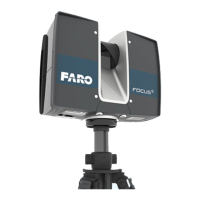
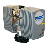
Toopenasinglefrontfaceofthecover,pulltheverticalVelcroflapsawayfromthedeviceandliftthefront
face.Forfreeaccesstothescannerinstandbymode,theopenedfrontfacecanalsobeflippedovertothe
topofthescanner.
Figure 3-8 : Opening the cover
FARO
®
FOCUS® Laser Scanner Accessories Manual
Chapter 3: Thermal Protection Covers
FARO FOCUS® LASER SCANNER (00.00) Page17of36