Note that, on the data selection screen for read, write, verify, and check operations, the values indicate the
capacity of the inverters as listed below.
Table 3.13 Inverter Models on Data Selection Screen
Symbol Inverter Model Symbol Inverter Model
FRN 5.5 LM1S-2
FRN 5.5 LM1S-4
5.5LM1-2 5.5LM1-4
FRN 7.5 LM1S-2
FRN 7.5 LM1S-4
7.5LM1-2 7.5LM1-4
FRN 11 LM1S-2
FRN 11 LM1S-4
11LM1-2 11LM1-4
FRN 15 LM1S-2
FRN 15 LM1S-4
15LM1-2 15LM1-4
FRN 18.5 LM1S-2
FRN 18.5 LM1S-4
18.5LM1-2 18.5LM1-4
FRN 22 LM1S-2
FRN 22 LM1S-4
22LM1-2 22LM1-4
30LM1-4 FRN 30 LM1S-4
* A box (
) represents one or more alphanumerics.
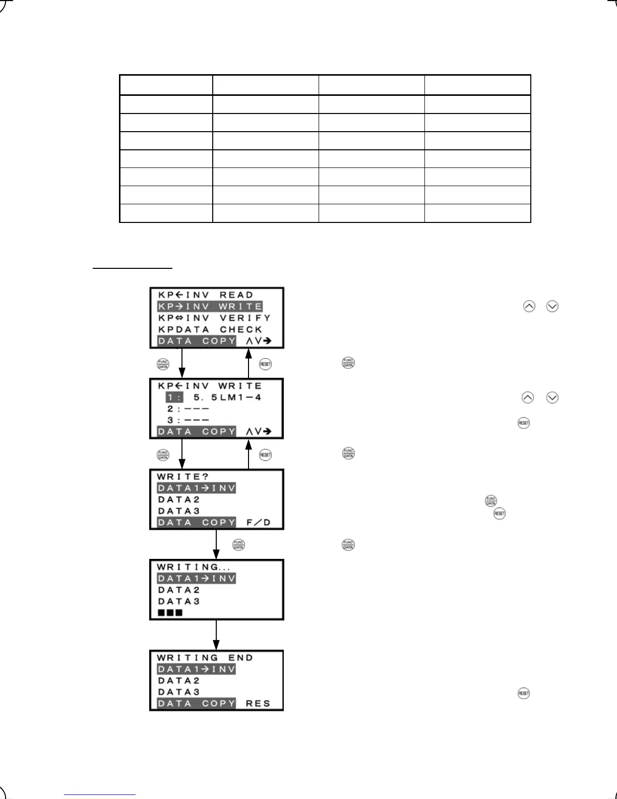
3) Write operation
List of data copy operations
Select the target operation by moving the cursor with
/
keys.
Data selection screen
Select the target data by moving the cursor with
/
keys.
To go back to List of data copy operations, press the key.
Confirmation screen
If "Write" is actually performed, the selected data will overwrite
the data held in the inverter. If OK, press the
key.
To go back to Data selection screen, press the
key.
"In progress" screen
A bar indicating progress appears in the bottom.
Completion screen
This screen indicates that Write operation has completed
successfully.
To go back to List of data copy operations, press the
key.
Figure 3.20 Screen Transition for "WRITE"
Press the key to establish the target operation.
Press the key to establish the target data.
Upon completion, Completion screen automatically appears.
Press the key to start Write operation.
3-30