Chapter 6 Description of Operations
PAGE 6-40
System Parameters (controller Information 1)
D-No.000 Torque controller Cannot be changed.
All fastening parameters within the controller will have the same torque unit.
D-No. 001 Software Version Cannot be changed.
This is the software version of the controller.
D-No. 002 Amplifier Version Cannot be changed.
This is the amplifier version.
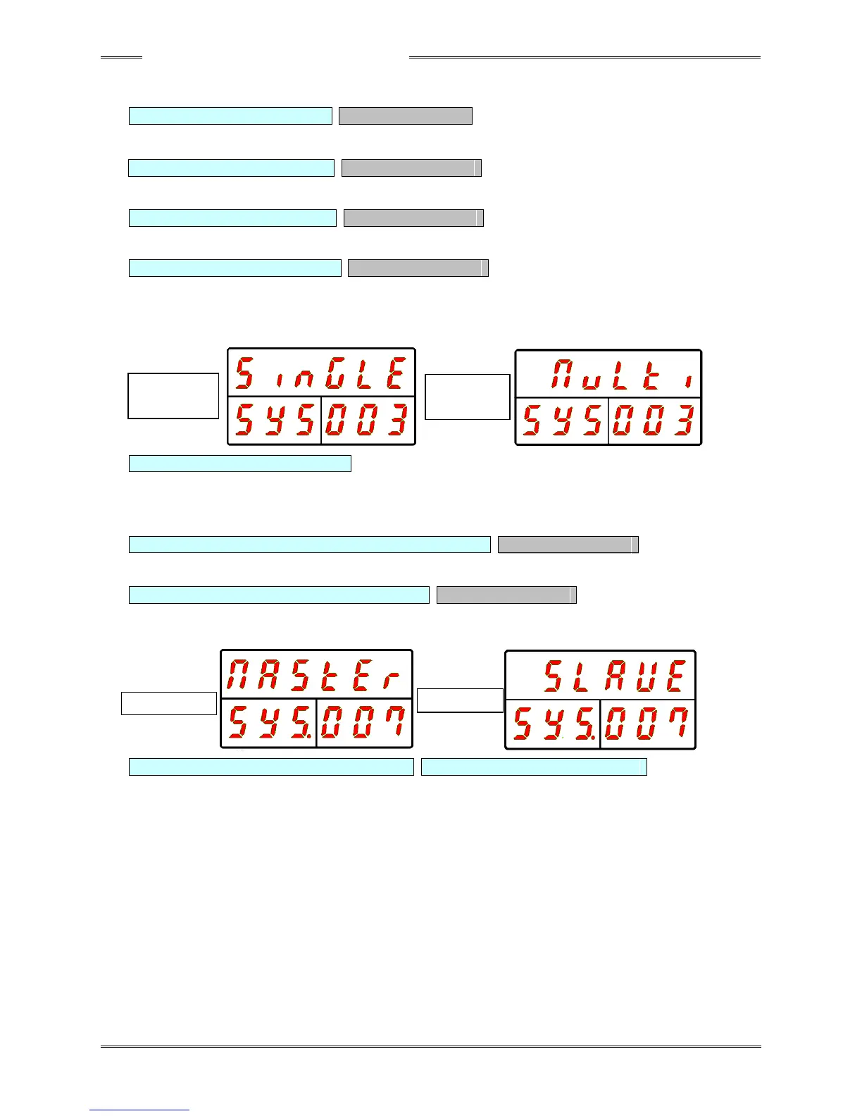
D-No. 003 System Indication Cannot be changed.
This indicates whether the controller is a multi system or a single system.
This is also used to change between the multi system and the single system.
The handheld tool operates only in the single system setting.
D-No. 004 External Gear Ratio Setting range: 0.300 ~ 3.000, standard setting: 1.000
When a gear is installed at the top of the tool, the gear ratio with respect to the output
shaft of the tool is set here.
Do not use a value other than 1.000 as long as an external offset gear is not used.
D-No.005 / 006 For adjustment by the manufacturer Cannot be changed.
Not used.
D-No. 007 Communication Axis Indication Cannot be changed.
This indicates whether the controller is the MASTER Axis for (PC) communication and
I/O (PLC) communication or is a SLAVE Axis.
D-No. 008 Axis Cycle Count (×1 million) D-No. 009 Axis Cycle Count (×1)
These indicate the count at which the controller performed the fastening operation.
* When the count is less than 1 million times, [------] is indicated for D-No. 008.