Chapter 9 External Interface
PAGE 9-26
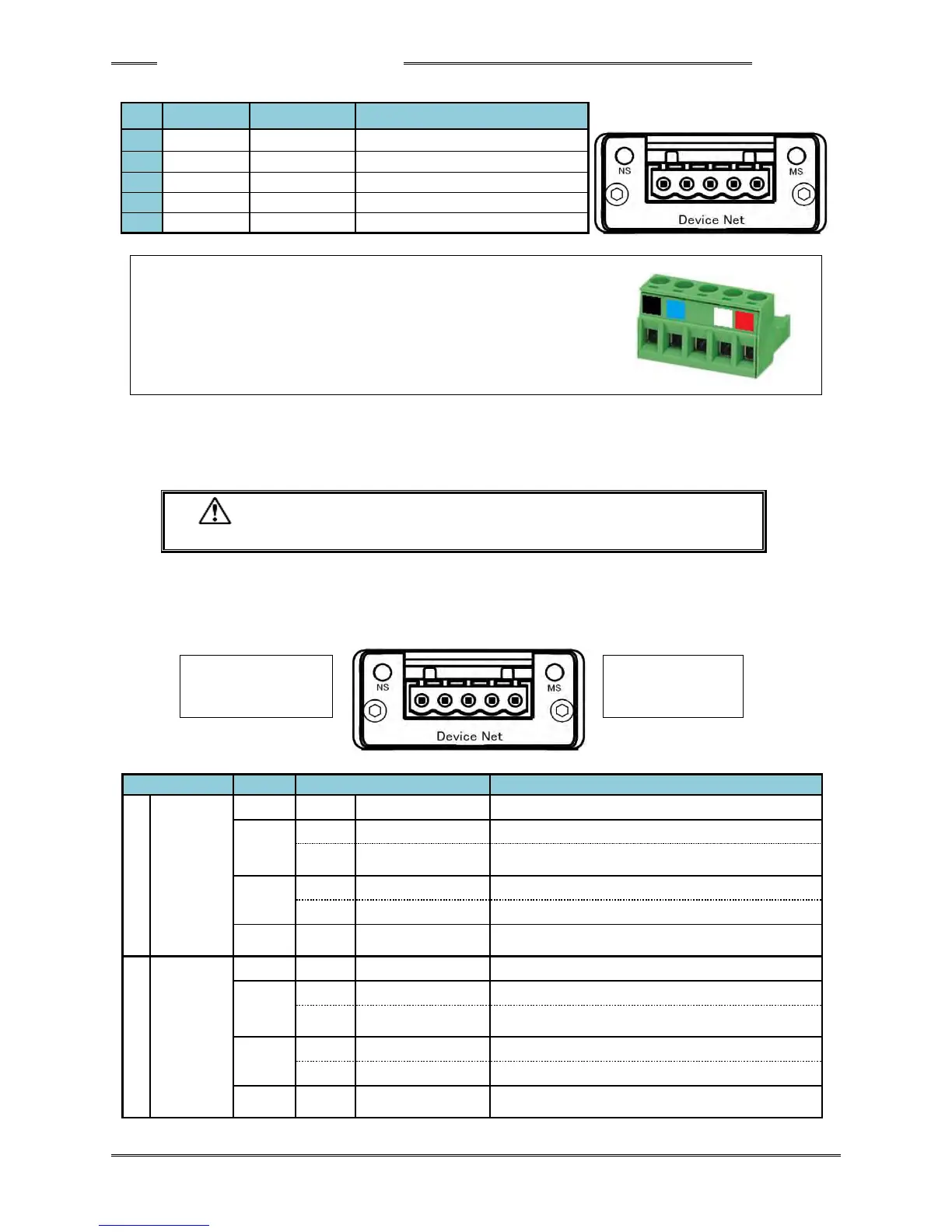
● Module Pin Configuration
Communication data Low side
Manufacturer: Phoenix Contact
Type: Connector plug
Model: MSTB 2.5/5-ST-5.08 AU M
Applicable wire size: AWG 14 ~ 23 or 0.25mm
2
~ 2.5mm
2
* The connector is provided with the equipment.
Please prepare the cable on your own.
However, the compatible wire size and recommended rod terminals (ferrules) are as follows.
・ Compatible wire size ・・・ AWG 23 ~ 14 (0.25mm
2
~ 2.5mm
2
)
・ Recommended rod terminals (ferrules)
・・・ Model: AI 2,5-6 WH (Phoenix Contact)
・ Be sure to connect the cable with all power being OFF.
● List of LED Indications
The module LEDs indicate the states of the nodes of the AFC3000 Device Net System and the network
state.
Offline or power is not supplied.
Although online, connection is unestablished.
A critical error has occurred.
A connection timeout has occurred once or more.
Due to incomplete configuration or connection failure, the
device must be re-recognized.
A critical error has occurred.
A recoverable error has occurred.