EasyManua.ls Logo

Feig Electronic TST FU3F-A - Tst Fu3 F

Feig Electronic TST FU3F-A
114 pages
Print Icon
To Next Page IconTo Next Page
To Previous Page IconTo Previous Page
Loading...
TST
Assembly instructions
FUF2 / FU3F-A/-C/-F
FEIG ELECTRONIC GmbH
Page 37 of 114
TST_FUxF-A-C-F_Montageanleitung_EN_15
5.2.2 TST FU3F
3~
M
W
V
U
P
E
AC
~
~
+
-
.
P
E
P
E
DC
30 31 32
P
E
T1 T2 T3
L
`
N
`
L
`
N
`
J
u
mp
e
r
C
o
n
n
e
c
t
i
o
n
e
x
a
mp
l
e
:
b
r
a
k
e
a
c
c
o
r
d
i
n
g
t
o
o
p
e
n
c
i
r
c
u
i
t
c
u
r
r
e
n
t
c
o
n
t
r
o
l
l
i
n
e
i
n
c
l
u
d
i
n
g
b
r
a
k
e
c
o
n
n
e
c
t
i
o
n
a
n
d
l
i
mi
t
s
wi
t
c
h
c
o
n
n
e
c
t
i
o
n
S
h
i
e
l
d
i
n
g
o
f
t
h
e
mo
t
o
r
c
a
b
l
e
B
r
a
k
e
r
e
c
t
i
f
i
e
r
Split ferrite
(742 727 22)
Split ferrite
(742 717 22 S)
Figure 13: Motor connection
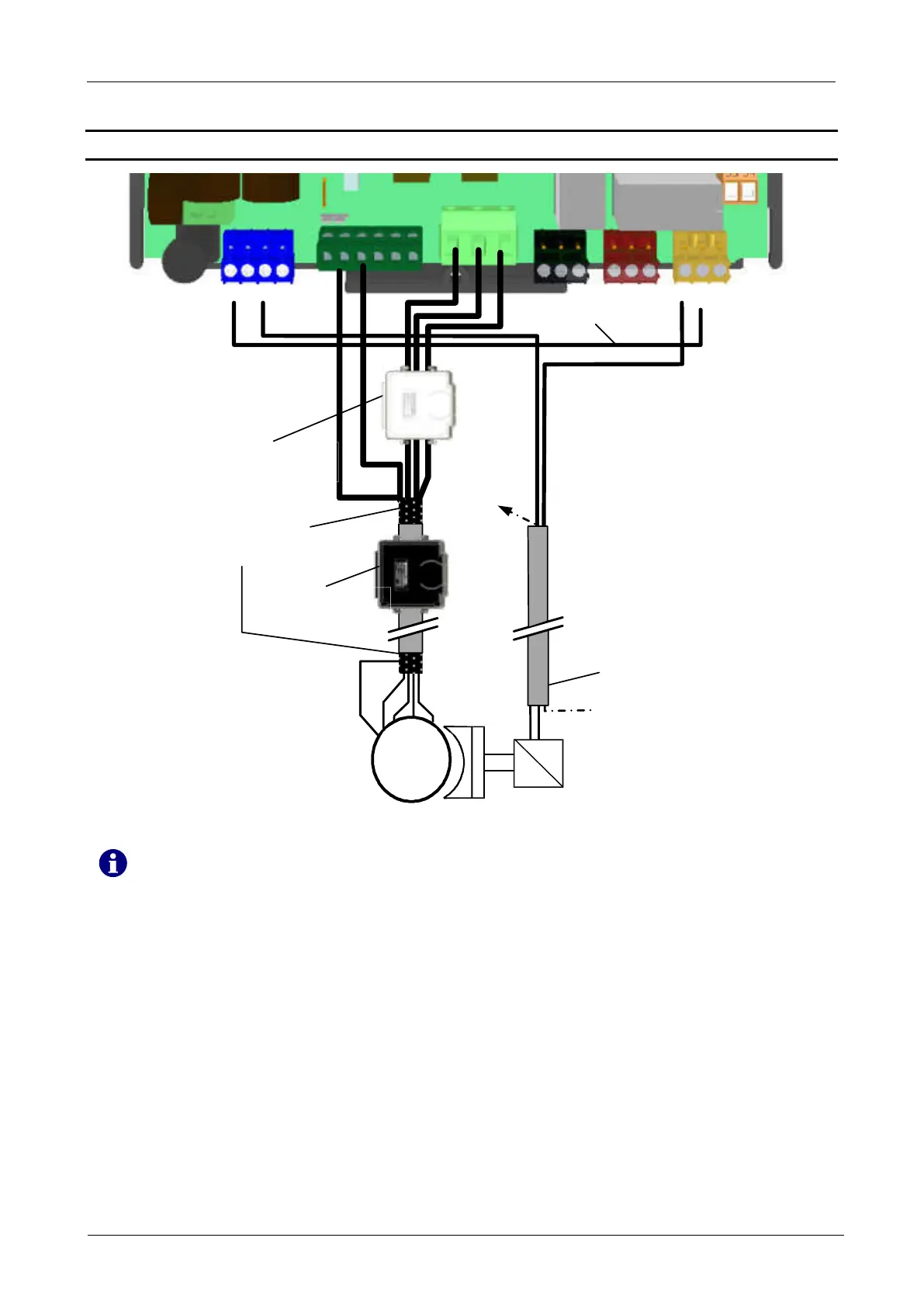
When connecting the motor cable, the enclosed split ferrite (grey, Würth number: 742
727 22) must be placed around the three wires (T1/T2/T3).
For variant -A (2, 2 kW), the wires T1/T2/T3 must be routed twice trough the split ferrite.
In the C- and F-Version (4 und 5 kW) the wires must be routed one time through the split
ferrite.
We recommend to place another split ferrite (black, Würth number: 74271722S) as
close as possible to the door controller around the complete motor cable. The black split
ferrite is not included in the scope of delivery!

Table of Contents

Related product manuals