33
Checking, adjusting and synchronizing U-brakes
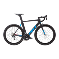
Many BMX bikes are equipped with a rotor (also known as a gyro) (a) connected to
the brake callipers, also referred to as U-brakes. Common U-brake designs have
two brake arms mounted separately on either side of the rim. When pulling the
brake lever, both arms are connected via the cable, and then pads touch the rim.
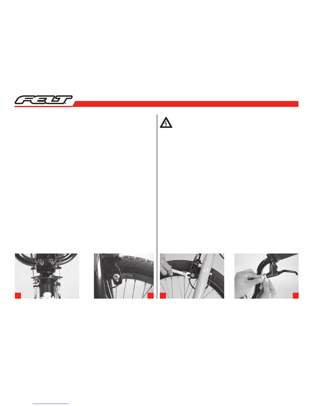
Check whether the brake pads are perfectly aligned with the rims (b) and still suf-
ficiently thick. You can judge the wear of the brake pads by the appearance of
the grooves. If the pads are worn down to the bottom of the grooves, it is time to
replace them.
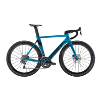
The brake pads should hit the rim simultaneously, both first touching it with the
front portion of their surface. At the moment of first contact the rear portion of the
pads should be a millimetre away from the rim. Viewed from the top the brake pads
form a “V“ with the trough pointing to the front. This V-shaped setting prevents
screeching when the brakes are applied. To align the brake pads, release the fixing
bolt, realign the pad and retighten the fixing bolt (c).
The brake lever must always remain clear of the handlebars. You should not be able
to pull it all the way to the handlebars, even in the event of an emergency stop.
A correctly adjusted brake will match all these points.
Adjusting the position of the brake pads relative to the rims requires a
considerable degree of skill. Replacing and adjusting the brake pads is a
job best left to your FELT dealer.
Adjustment
The brake cable of U-brakes with a rotor system installed is composed of several
sections, all of which must be checked and adjusted. First of all, release the coun-
ter nut on the callipers adjusting devices; then unscrew the adjusting bolt until the
cable tension meets your requirements. Finish by keeping the bolt stationary, while
tightening the counter nut against the limit stop. The brake only works properly,
when all sections are adjusted accurately – a job for a skilled mechanic.
Lever adjustability
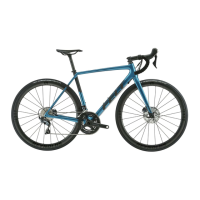
To adjust the brakes at the lever, release the knurled lock ring located at the point
where the brake cable enters the brake lever on the handlebars. Release the
knurled, slotted adjusting bolt by a couple of turns (d). In this way you shorten
the free travel of the brake lever. Keeping the adjusting bolt fixed, tighten the lock
ring against the brake lever mount. This prevents the adjusting bolt from coming
loose.
Ensure that the slot of the bolt faces neither forward nor upward, as this would
permit water or dirt to enter.
a b c d