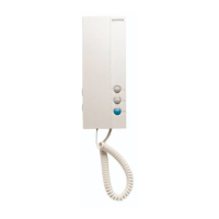
12.2.2 Door Lock Controlled with potential free relay
Note:
1. Use an external power supply (PSU)
according tothe electrical lock's
consumption.
2. The jumper must be taken off before
connecting.
3. Establish the connected lock-release
mode (See chapter 11.2):
•
Normal open realay type:
Unlock Mode = 0 (by default).
•
Normal closed relay type:
Unlock Mode = 1.
LOCK
Take off the Jumper
POWER
SUPPLY
BUS PL S
+
S-
12.2 Electric Lock Connection
Note:
1. Electronic lock fail secure type
should be used.
2. The door lock is limited to 12Vdc,
and holding current must be less
than 250mA.
3. The door lock control is not timed
from the Exit Button (EB).
4. The lock-release must be
confi gured as a normal operating
lock-release. See chapter 11.2.
5. When connect in Electronic lock,
put the jumper in position in 1-2.
EB
*
LOCK
PL S
+
S-
connect Electronic lock, the jumper position in 2-3.
BUS
1 2 3
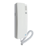
12.2.1 Door Lock Controlled with Internal Power
Exit
Button
1
23
1
23
EB
*
LOCK
PL S
+
S-
connect Electronic lock, the jumper position in 2-3.
BUS
1 2 3
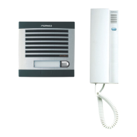
relay
Exit
Button
An intermediate relay should be
connected for equal or higher
voltages of 20V, otherwise the panel
will be damaged.
1
23
_ _ _ _ _ _ _ _ _ _ _ _ _ _ _ _ _ _ _ _ _ _ _ _ _ _
1-2.
For installations with a motorized door, please
follow this method of connection.
-12-