Do you have a question about the Ferroli ECOTRONIC Plus and is the answer not in the manual?
Instructions for physically attaching the controller unit to a wall or mounting panel.
Details on connecting sensors, bus interfaces, and mains power to the controller.
Describes the connection and types of relays for output control.
Explains VBus and RS232 interfaces for data communication and PC connection.
Details on the power supply requirements and connection for the controller.
Explains the function of the three control buttons for navigating menus and adjusting values.
Describes the status indications provided by the controller's red/green LED.
Illustrates the hierarchical structure of the controller's menus and submenus.
Details the different user access levels (Expert, User, Customer) and their associated codes.
Provides a visual diagram of the controller's menu navigation and available options.
Step-by-step guide for initial setup, including system adjustment and sensor/relay allocation.
Overview of the 7 pre-programmed basic solar systems and their hydraulic configurations.
Explains how to assign functions like thermostat, timer, and differential control to available relay outputs.
A comprehensive guide to configuring the controller's settings based on system requirements.
Tables detailing the assignment of sensors and relays for various system variants.
Configuration settings for solar system operation, including system type and hydraulic variants.
Details on selecting the sensor for monitoring bypass conditions in the solar circuit.
Functionality for linking circuits separated by an external heat exchanger.
Enables diverting surplus solar energy from the collector when the store reaches maximum temperature.
Activates a circuit to protect the system medium from freezing when collector temperature drops.
Controls pump speed based on collector temperature for maintaining a set target.
Activates a function to check temperatures for legionella control at specific times.
Monitors store temperature using two sensors to control switch-on and switch-off levels.
Details on assigning thermostat, timer, and differential functions to available relay outputs.
Enables control of two independent weather-compensated heating circuits.
Controls the mixing valve position based on flow temperature difference.
Calculates heat quantity using flow and return temperatures without a flowmeter.
Calculates heat quantity using flowmeter data and temperature differences.
Sets parameters for antifreeze types and fluid concentration for heat transfer.
Displays a message for high temperature differentials in solar loading.
Activates a relay to signal detected faults like sensor defects or RTC malfunctions.
Activates a function that opens the heating circuit for flue gas measurement.
Allows adjustment of sensor readings to compensate for minor inaccuracies.
Enables manual control of relays, allowing them to be switched on, off, or set to automatic.
Describes precision-platin sensors (PT1000) used with the controller, including types and cables.
Details the CS10 solar cell used for detecting irradiation intensity.
Explains the V40 instrument for detecting water/glycol flow and its use with calorimeters.
Information on the RTA11-M for adjusting heating curves and functions remotely.
Describes the FAP12 sensor for measuring outdoor temperature for weather-compensated heating.
Checks power supply and fuse replacement procedures if the controller is not working.
Identifies errors related to broken or short-circuited sensor cables and displays error codes.
Lists and explains various error and warning messages displayed by the controller.
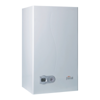
| Mounting | Wall-mounted |
|---|---|
| Max Operating Pressure | 3 bar |
| Flue Diameter | 60/100 mm |
| Fuel Type | Gas |
| Water Connections | G 3/4" |
| Dimensions (HxWxD) | 700x400x299 mm |