1. Installation
1-13
Festo P.BE-CTEU-EC-OP+MAINT-EN en 1208NH
Fieldbus interface – connection technology and pin
allocation
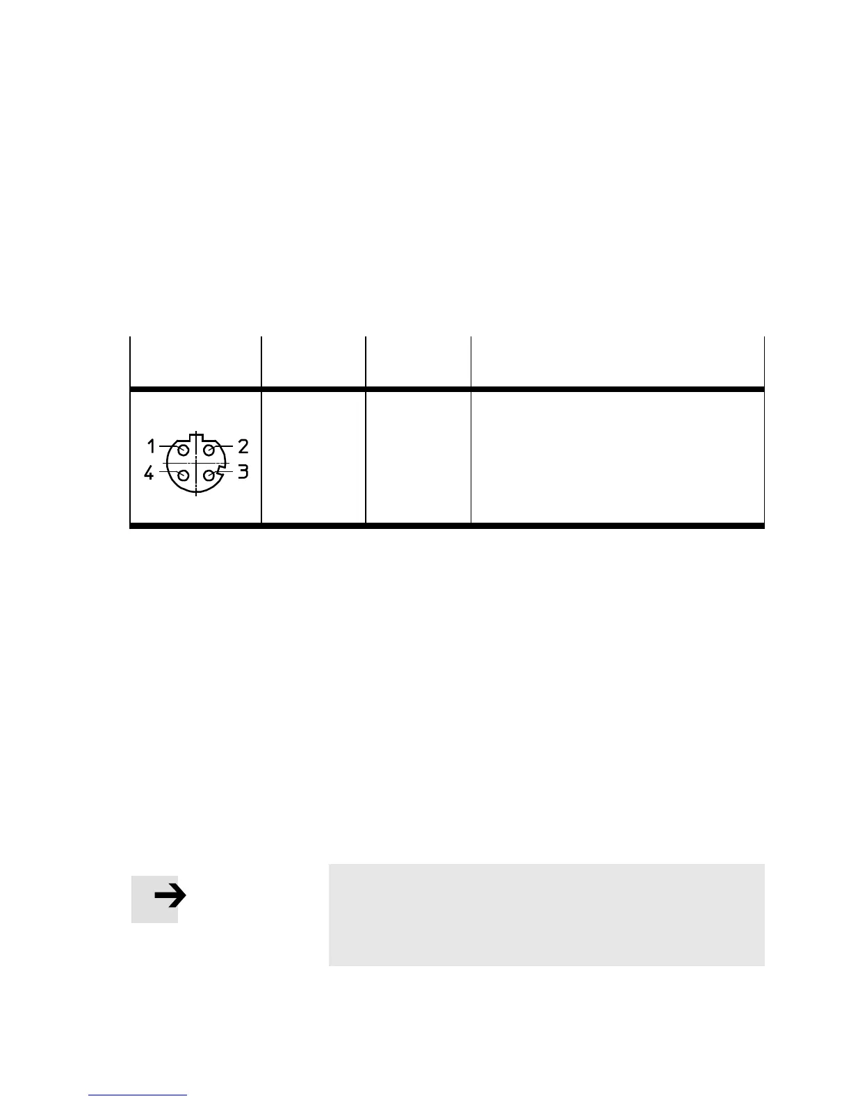
There are two 4-pin M12 socket plug connectors with
D-coding (for industrial Ethernet use, corresponding to
IEC 61076-2-101) for connecting the bus node to the fieldbus.
Socket
(M12, D-coded)
Pin Allocation
(signal)
Explanation
1
2
3
4
Housing
TD+
RD+
TD–
RD–
FE
Transmission data (transmit data, TD) +
Receivedata(receivedata,RD)+
Transmitted data –
Received data –
Shield/functional earth (FE)
Tab. 1/2: Pin assignment of the network interface
Fi e ldbu s connecti ng cable – speci fi cati ons and confi gu r atio n
•
Use shielded industrial Ethernet round cable of cat-
egory Cat 5 or higher.
– Cable length:
max. 100 m between network partici pants
(corresponding to specifications for Ethernet net-
works, ISO/IEC 11801 and ANSI/TIA/EIA-568-B).
– Wire cross section for max. line length:
22 AWG (for 100 m link length, based on
ISO/IEC 11801).
Note
If installation has not been carried out correctly and if high
baud rates are used, data transmission errors may occur
as a result of signal refl ections and attenuations.