2. Commissioning
2-8
Festo P.BE-CTEU-EC-OP+MAINT-EN en 1208NH
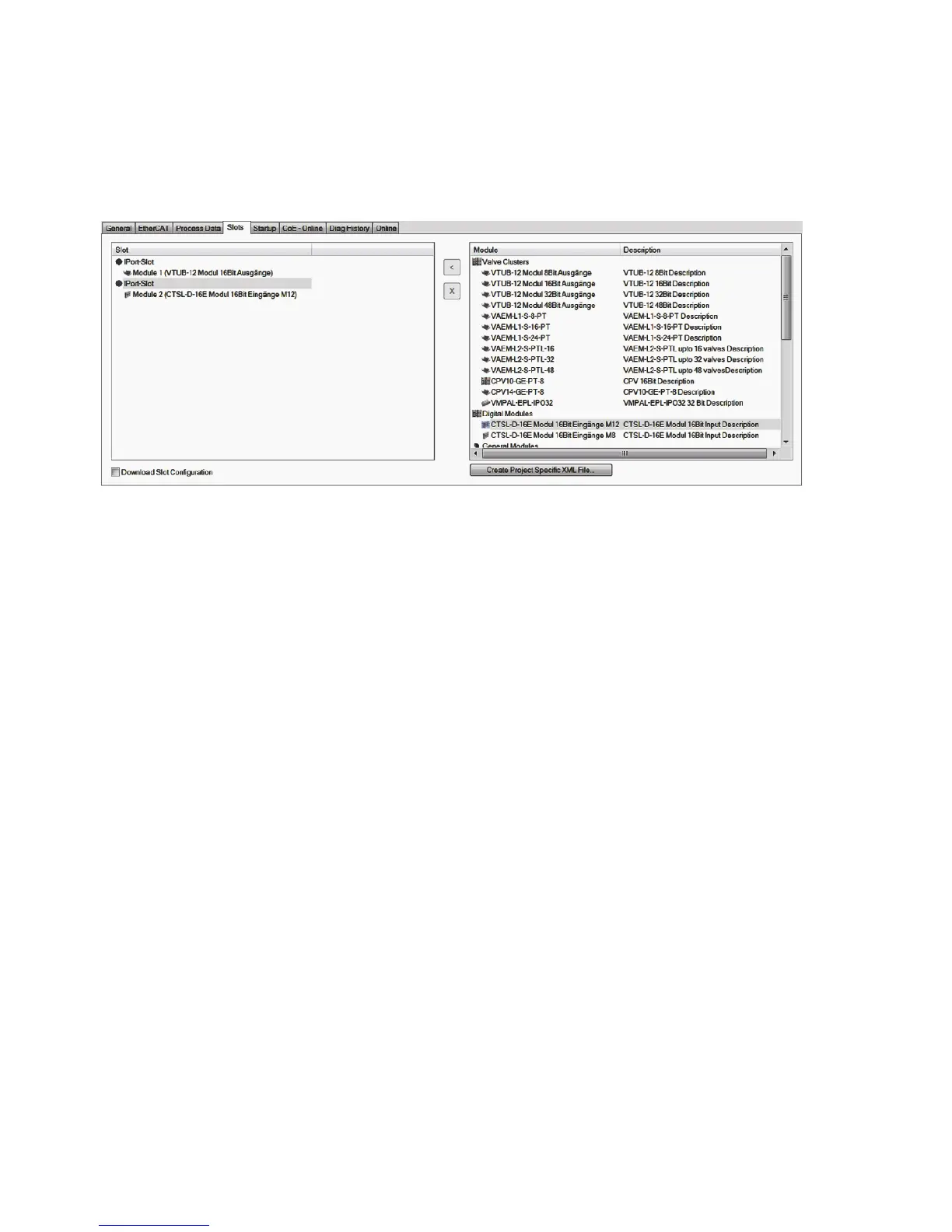
Fig. 2/1: Example: configuratio n for a valve terminal and an input module in auto mode
Tool change mode
In tool change mode, only the data width of each I-port is
defined; the specific components that can be connected are
not.
The startup parameters are configured by activating tool
change mo de for each I-port and defining the data width. Th i s
ensures that the correct module configuration, i.e. data
width, is requested after each startup. Each I-port is assigned
a fixed I/O data length.
The I/O data lengths are configured via the CoE objects
0x8200 and 0x820A ( section A.4). The I/O data length for
both I-ports must not exceed 16 bytes. If the image table ex-
ceeds the defined I/O data length, the excess bytes will be
excluded. If the modular ESI file is used, the number of bytes
must correspond to the formula 2
n
where n = 0, 1, 2, 3 or 4
(i.e.: 1, 2, 4, 8 or 16 bytes).
The connected I-port devi ces can be exch anged freely. No
diagnostics messages are generated wh en devi ces are re-
placed. Only if the I-port configuration “expect device” is se-
lected is the message
“Output data size is greater than configured” generated when
a device with an I/O length greater than that co nfi gured in
tool change mode is connected ( section 2.1.4).
 Loading...