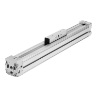
DGP(L)−...−B
Festo DGP(L)−...−B 0609g English
30
With stroke lengths > 500 mm:
If the DGP(L)−... is controlled by the SPC11 or SPC200, the compressed air
must be provided on both sides (feature D2).
Only bilateral air supply will guarantee optimum dynamics.
Fitting the electric components
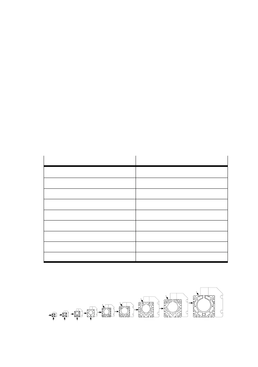
If you are using proximity switches to scan positions:
S Make
sure that the minimum distance L between static or moving ferritic
masses and the proximity switches corresponds to the values specified in
Fig.20.
In this way you will avoid incorrect switching as a result of external influences.
j
L
DGP(L)−80−B 5.0 mm
DGP(L)−63−B 14.0 mm
DGP(L)−50−B 11.4 mm
DGP(L)−40−B 5.6 mm
DGP(L)−32−B 4.8 mm
DGP(L)−25−B 4.2 mm
DGP(L)−18−B 40.0 mm
DGP(L)−12−B 30.0 mm
DGP(L)−8−B 20.0 mm
Fig.20
S Place the proximity switches as follows:
Fig.21
8 12 18 25 32 40 50 63 80