5. Maintenance and conversion
5−34
Festo P.BE−MPA−EN en 0910d
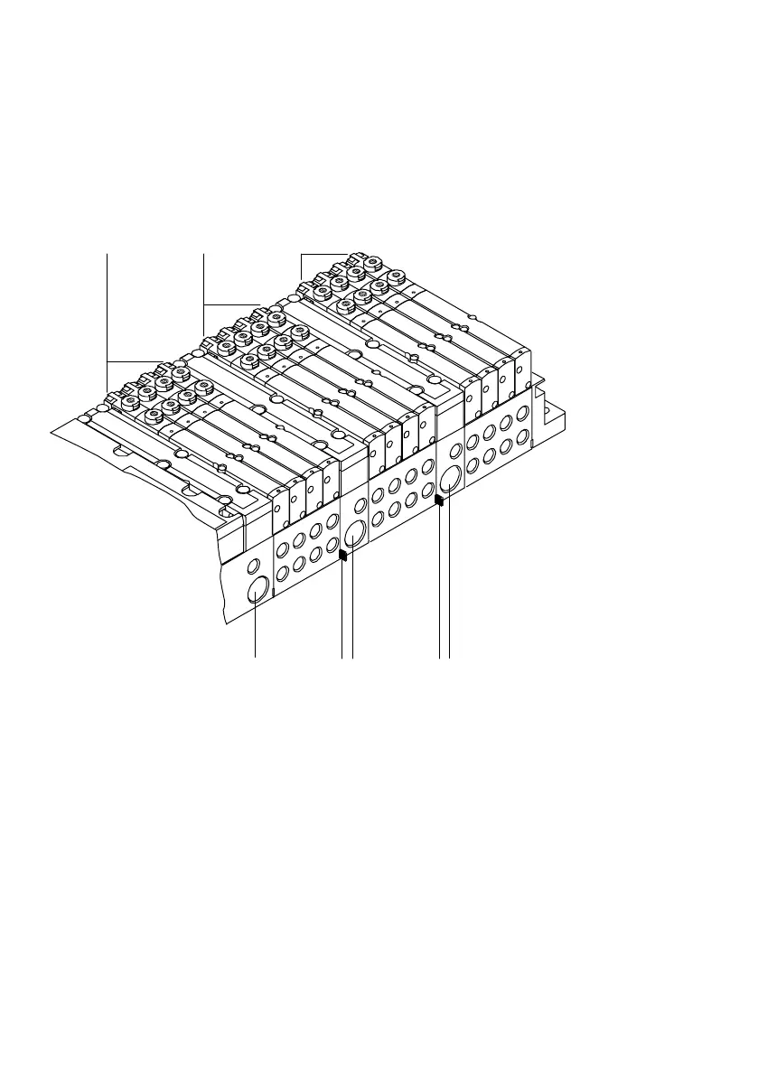
The following diagram shows the structure of pressure zones
usi ng as an example an MPA−S valve terminal with CPX terminal.
12
3
4567
5
1
Valve sub−bases of the 1st. pressure zone
2 Valve sub−bases of the 2nd. pressure zone
3 Valve sub−bases of the 3rd. pressure zone
4 Supply unit with connection (1) for supplying compressed air to the 3rd
pressure zone
5 Marking of the separating seal with pressure zone separation
6 Supply plate with connection (1) for supplying compressed air to the 2nd
pressure zone
7 Pneumatic interface with connection (1) for supplying compressed air to the 1st
pressure zone
Fig.5/16: Example of MPA−S valve terminal with CPX terminal and 3 pressure zones
 Loading...


