1. Summary of components
1−31
Festo P.BE−MPA−EN en 0910d
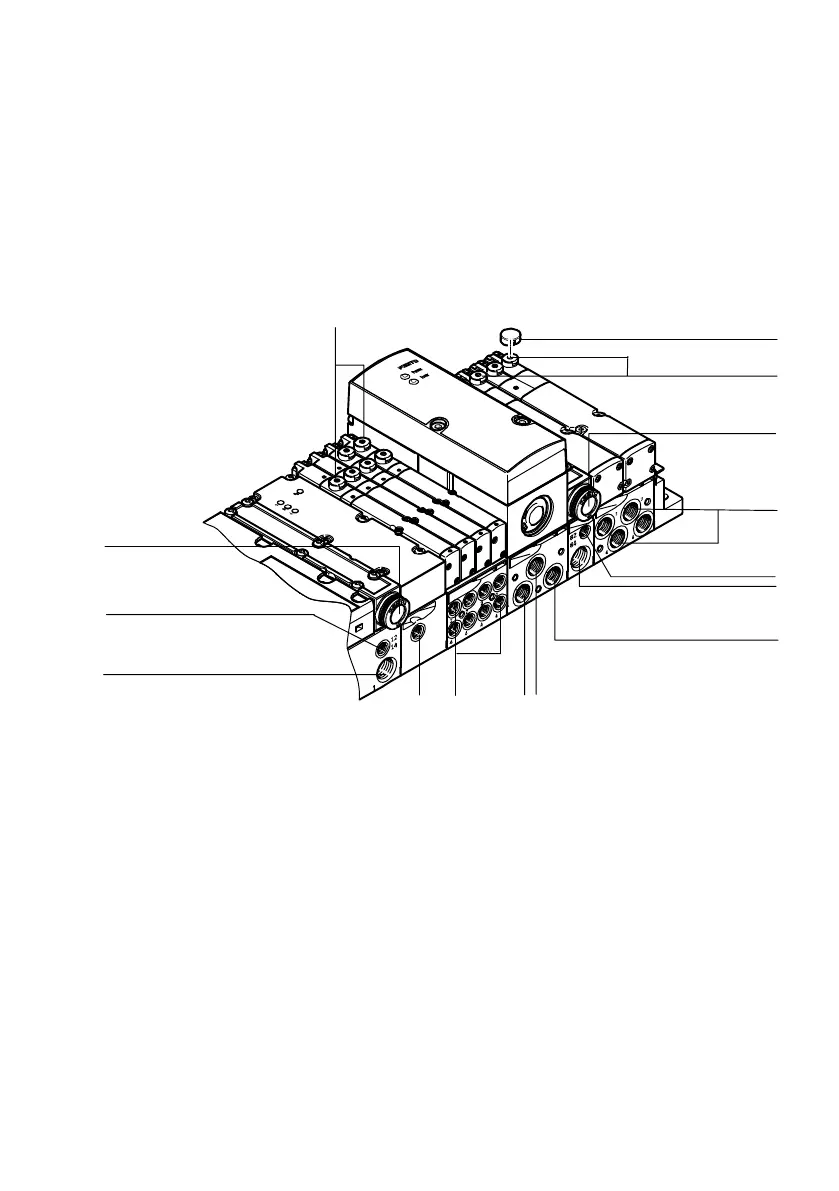
1.1.3 Connection and display components
You will find the following pneumatic connecting, display and
operating elementson the M PA−S valve terminal:
7
2
3
5
6
1
4
1
8
9aJ
6
3
4
aA
1 Manual override (per pilot solenoid,
turning/locking or non−locking)
2 Manual override cover cap
3 Common exhaust connection (3/5),
Valves"
4 Working lines (2) and (4) per valve
5 Connection (82/84) only with variant
for ducted exhaust, Pilot exhaust"
6 Supply port (1),
Operating pressure"
7 Pressure output (2) of the
proportional pressure regulator
8 Exhaust (3) of the proportional
pressure regulator
9 Pressure input (1) of the proportional
pressure regulator
aJ External pressure input of pressure
sensor type VMPA−FB−PS−P1
aA Pilot connection (12/14),
External pilot air supply"
Fig.1/13: Pneumatic connecting and operating elements of the MPA−S valve terminal