3. Installation
3−15
Festo P.BE−MPA−EN en 0910d
1
234
5
67
(12/14)
(1)
(1) (1)
(3/5) (3/5)
(3/5)
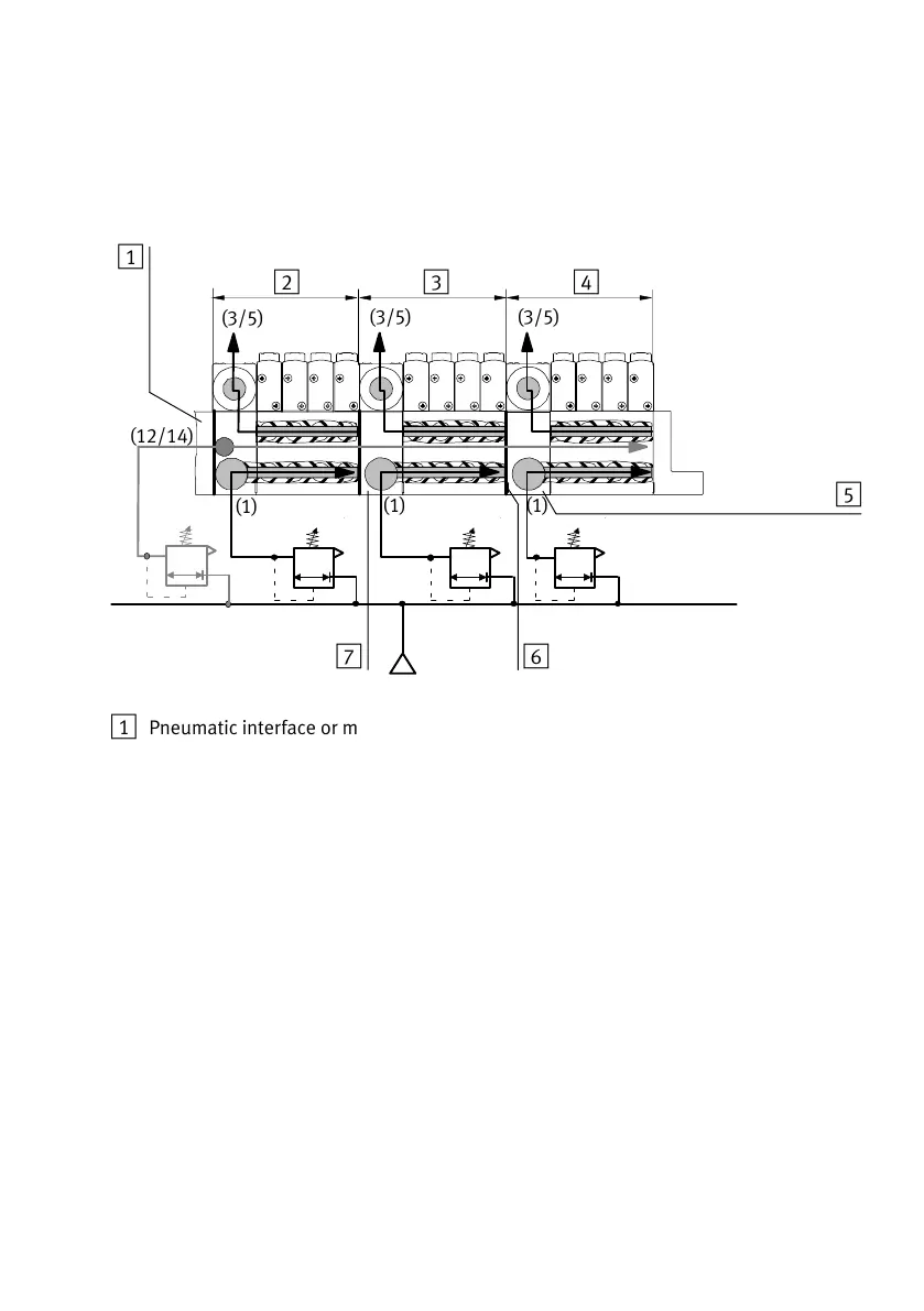
1 Pneumatic interface or multiple
connector plate with supply port (1)
for pressure zone 1 and pilot
connection (12/14) for the complete
valve terminal
2 Pressure zone 1
3 Pressure zone 2
4 Pressure zone 3
5 Air supply plate for pressure zone 3
6 Identification of the pressure zone
separating seal (projecting flag)
7 Air supply plate for pressure zone 2
Fig.3/3: Example of MPA−S valve terminal with 3 pressure zones