3. Installation
3−24
Festo P.BE−MPA−EN en 0910d
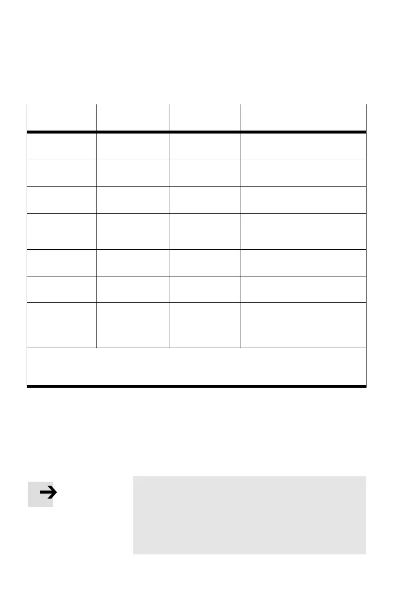
line Connection code
(ISO 5599)
Connection size
(ISO 228)
Connection
1)
Compressed air or
vacuum
(1) G¼" Fitting in electrical interface or in
the pneumatic supply plate
Pilot air (external
pilot air supply)
(12/14) M7 Fitting in electrical interface or in
the multiple connecto plate
Ducted exhaust
air from the valves
(3/5) QS10 Fitting in exhaust plate
2
)
Ducted exhaust
from the pilot
control
(82/84) M7 Fitting in the supply plate
2)
Work air or
vacuum
(2) or (4) MPA1: M7
MPA2: GÁ"
Fitting in the sub−base
Connection for
external pressure P1 M7
Fitting in pressure sensor plate
typeVMPA−FB−PS−P1
Supply port
Pressure output
Exhaust of the
VPPM−6TA
(1)
(2)
(3)
G ¼"
G ¼"
G ¼"
Fitting in the sub−base of the
proportional pressure regulator
1)
Depending on what you have ordered, the M PA−S valve terminal may already be fitted
with QS fittings.
2)
Only with MPA−S valve terminals with exhaust plate or supply plate.
Tab.3/4: Assignment of the connections
Observe the following instructions on installing the
pneumatic components. Only then can you guarantee
trouble−free operation.
Note
In the case of several systems with centrally ducted
exhaust air:
· Use non−return valves in the common exhaust lines (3/5)
or (82/84) in order to prevent functional impairment due
to back pressures.