Reproduction forbidden without Fibocom Wireless Inc. written authorization - All Rights Reserved.
FM350-GL Hardware Guide Page 35 of 67
The differential signal pair lines shall be parallel and equal in length;
The differential signal pair lines shall be short if possible and be controlled within 7 inch (177.8 mm)
for AP end;
The impedance of differential pair lines is recommended to be 85Ω. All the impedance of differential
pair should meet PCIe Gen3 protocol requirement of 70 to 100Ω;
It shall avoid the discontinuous reference ground, such as segment and space;
When the differential signal lines go through different layers, the via hole of grounding signal should
be in close to that of signal, and generally, each pair of signals require 1-3 grounding signal via holes
and the lines shall never cross the segment of plane;
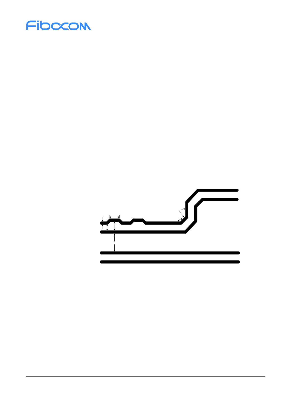
Try to avoid bended lines and avoid introducing common-mode noise in the system, which will
influence the signal integrity and EMI of difference pair. As shown in Figure 3-14, the bending angle
of all lines should be equal or greater than 135°, the spacing between difference pair lines should be
larger than 20mil, and the line caused by bending should be greater than 1.5 times line width at least.
When a serpentine line is used for length match with another line, the bended length of each segment
shall be at least 3 times the line width (≥ 3W). The largest spacing between the bended part of the
serpentine line and another one of the differential lines must be less than 2 times the spacing of normal
differential lines (S1 < 2S);
Figure 3-14 Requirement of PCIe line
The difference in length of two data lines in difference pair should be within 5mil, and the length match
is required for all parts. When the length match is conducted for the differential lines, the designed
position of correct match should be close to that of incorrect match, as shown in Figure 3-15. However,
there is no specific requirements for the length match of transmit pair and receiving pair, which means
the length match is only required by intra differential pair rather than inter differential pair.
 Loading...