Reproduction forbidden without Fibocom Wireless Inc. written authorization - All Rights Reserved.
FM350-GL Hardware Guide Page 45 of 67
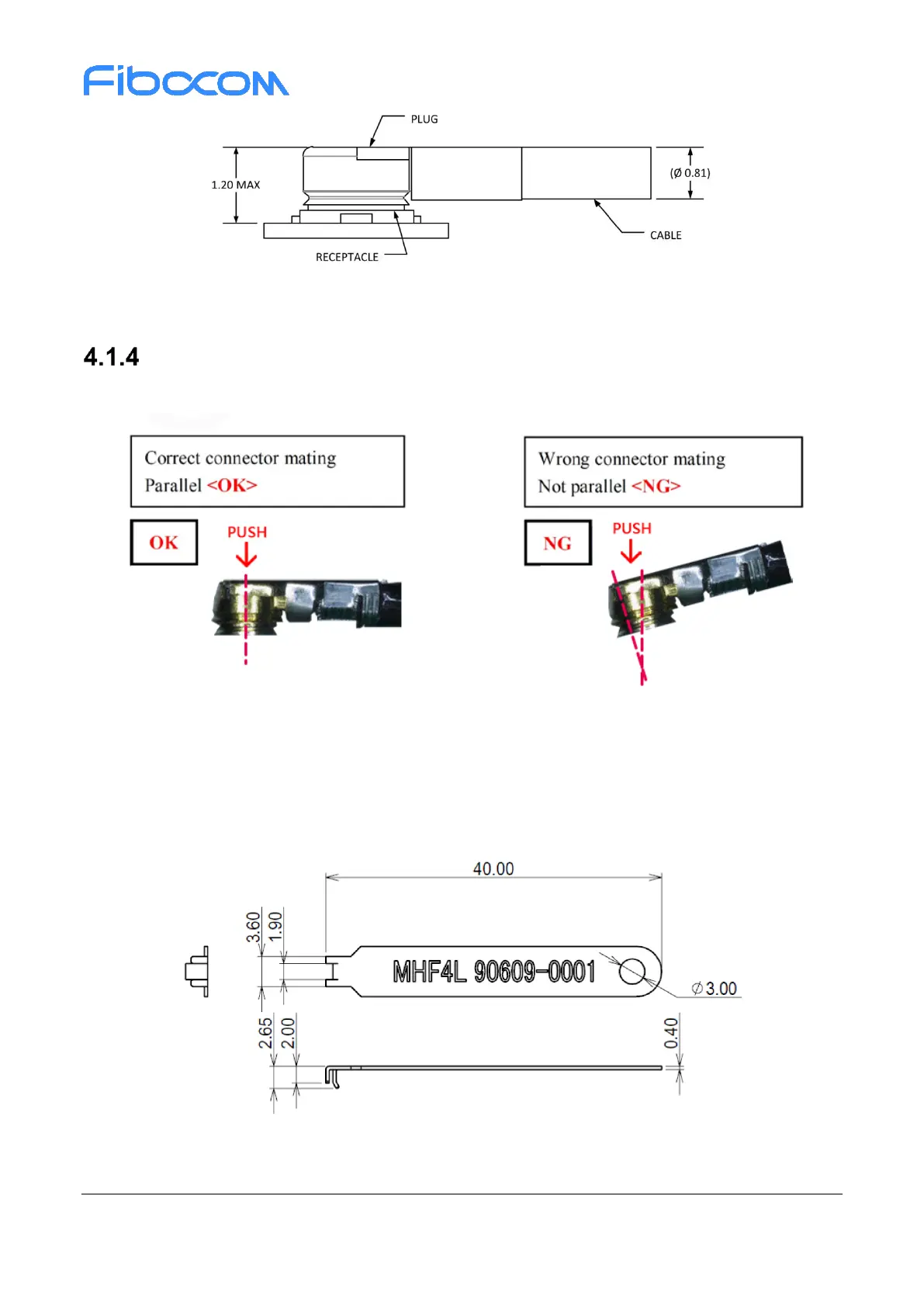
Figure 4-4 Schematic diagram of 0.81mm coaxial antenna connected to the RF connector
RF Connector Assembly
Mate RF connector parallel refer Figure 4-5, do not slant mate with strong force.
Figure 4-5 Mate RF connector
To avoid damage in RF connector unmating, it is recommended using pulling JIG as Figure 4-6, and the
pulling JIG must be lifted up vertically to PCB surface (see Figure 4-7 and 4-8).
Figure 4-6 Pulling JIG
 Loading...