Reproduction forbidden without Fibocom Wireless Inc. written authorization - All Rights Reserved.
FM350-GL Hardware Guide Page 36 of 67
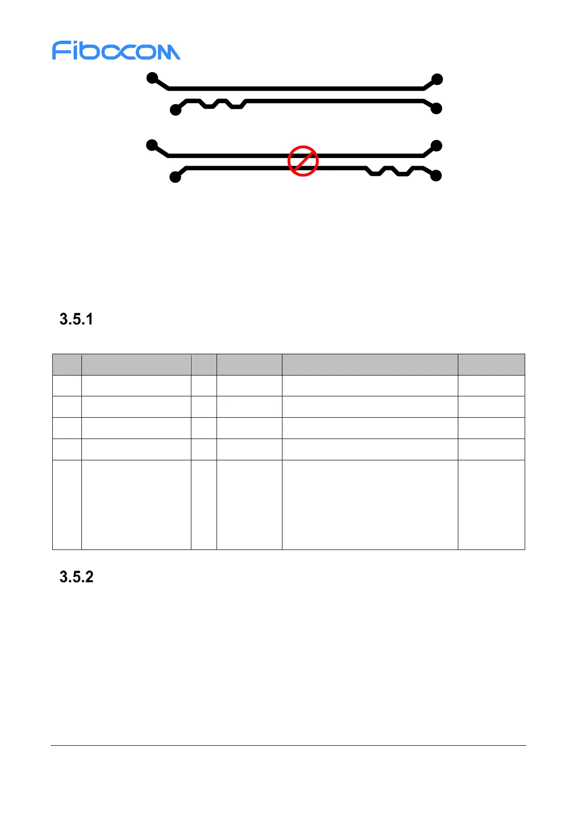
Correct match
Dismatched end
Incorrect match
Matched end
Figure 3-15 Length match design of PCIe difference pair
3.5 USIM Interface
The FM350 module supports dual SIM, one is a built-in eSIM and another is a SIM card interface. The SIM
interface supports 1.8V and 3V SIM cards.
USIM Pins
The USIM1 pins description is shown in the following table:
USIM data, internal pull up(4.7KΩ)
USIM card detect, internal 390K pull-
up.
Active high, and high level indicates
SIM card is inserted; and low level
indicates SIM card is detached.
USIM Interface Circuit
3.5.2.1 N.C. SIM Card Slot
The reference circuit design for N.C. (Normally Closed) SIM card slot is shown in Figure 3-16: