Twinflex V3 Control Panel Engineering and Commissioning Manual
18
Twinflex Repeater Panel
Installation 1
st
Stage
This unit is classed as ‘secondary indicating equipment’ (as stipulated in the British Standards). It is
available in 8 or 16 zone formats and has the optional functionality to provide system controls (silence,
reset and evacuate). The main control panel controls and indication will not be affected or hidden.
Fix the back box in a suitable position using the three screw holes provided remembering to allow enough
space for the correct termination of the appropriate cables.
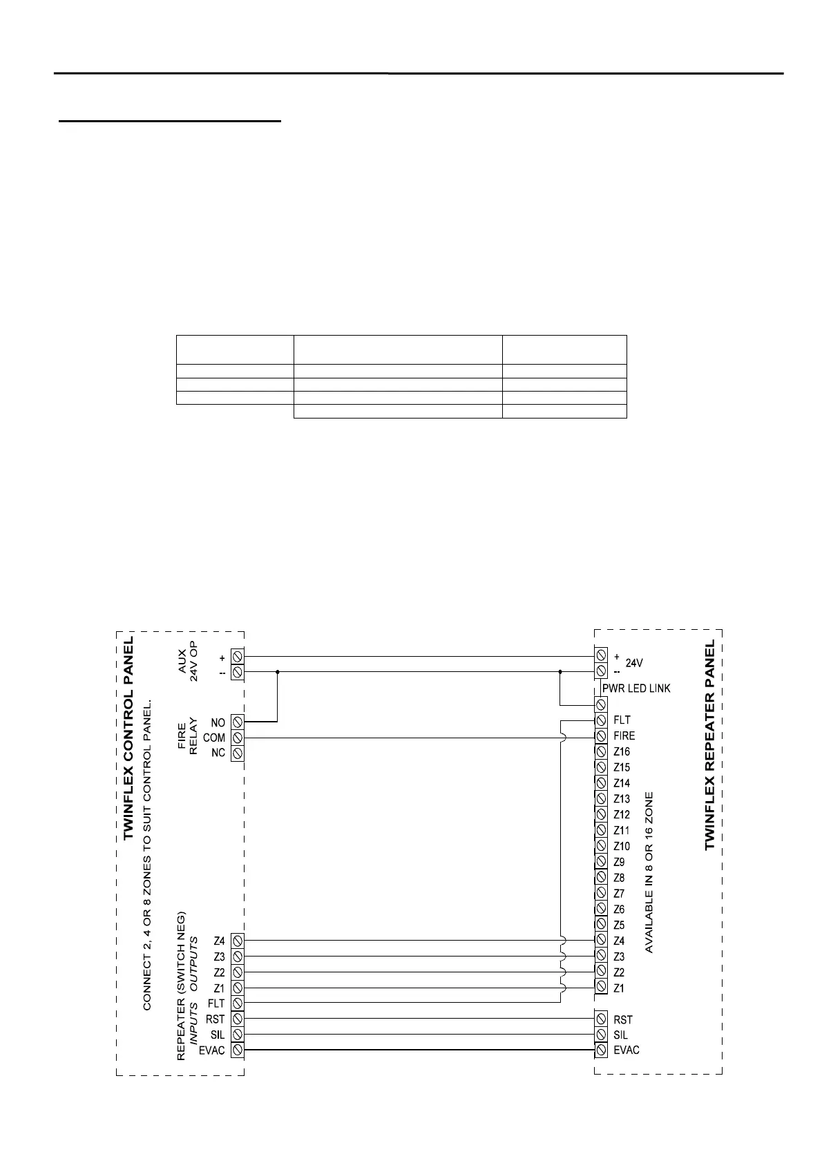
The repeater panel requires a multi-core cable from the main control panel, and must consist of the
following:
Number of Cores Function Example 8 zone
repeater
2 24V DC power supply 2
5 Silence, reset, evacuate, fire and fault 5
1 Per zone indication required 8
Example Total 15
Please remember that all high voltage testing must be carried out before the installation of any electronic
devices as this may cause damage. The installer needs to provide proof of zone continuity readings etc., to
enable commissioning to proceed.
Installation 2nd Stage
Once all testing has been carried out on the cabling and ‘continuity & integrity’ has been proven, then the
repeater panel may be assembled.
Connections