Twinflex V3 Control Panel Engineering and Commissioning Manual
9
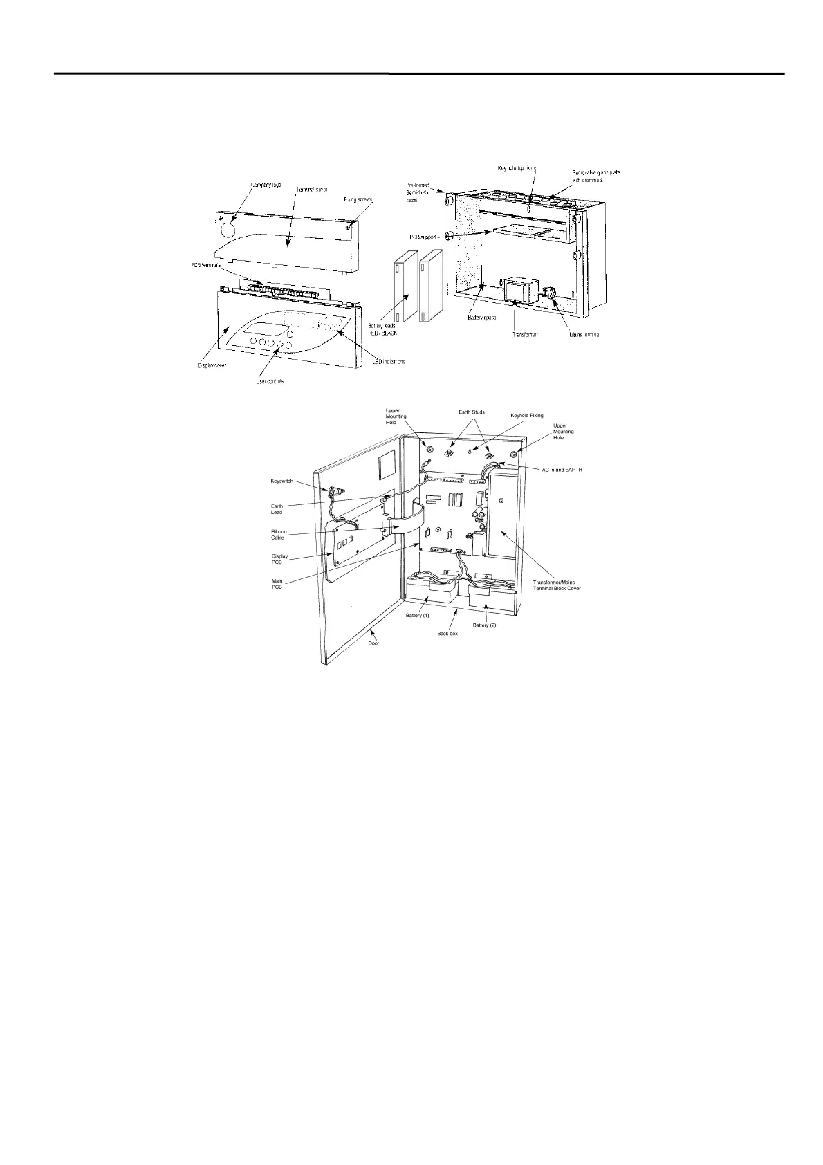
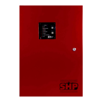
General Assembly
2 & 4 Zone Panels
8 Zone Panels
Topology & Cabling
All system wiring should be installed to comply with BS 5839 : Pt 1 : 2002 and BS 7671 (wiring regulations)
and any other standards relevant to the area or type of installation. A cable complying with the BS 5839 : Pt
1 : 2002 Category 1 (cables required to operate for prolonged periods during fire conditions) is required.
This must be a 2-core 1.5mm
2
screened fire resistant cable (ie. MICC, FP200, Firetuff, Firecell, Lifeline or
equivalent).
Each zone requires a separate 2-core radial circuit from the control panel to the furthest point of the zone,
to a maximum of 500 metres.
In order to protect against possible data corruption it is important ensure the following points are adhered
to:
1. The cable screen must be connected to earth/ground at the control panel only.
2. The cable screen must not be connected to earth/ground at any point other than the control
panel, ie. do not connect the screen to a device back box.
3. The cable screen continuity must be maintained at every point of the circuit, using the
terminals provided or a suitable connection block.
Refer to the following System Wiring Schematic for further details.