Twinflex V3 Control Panel Engineering and Commissioning Manual
44
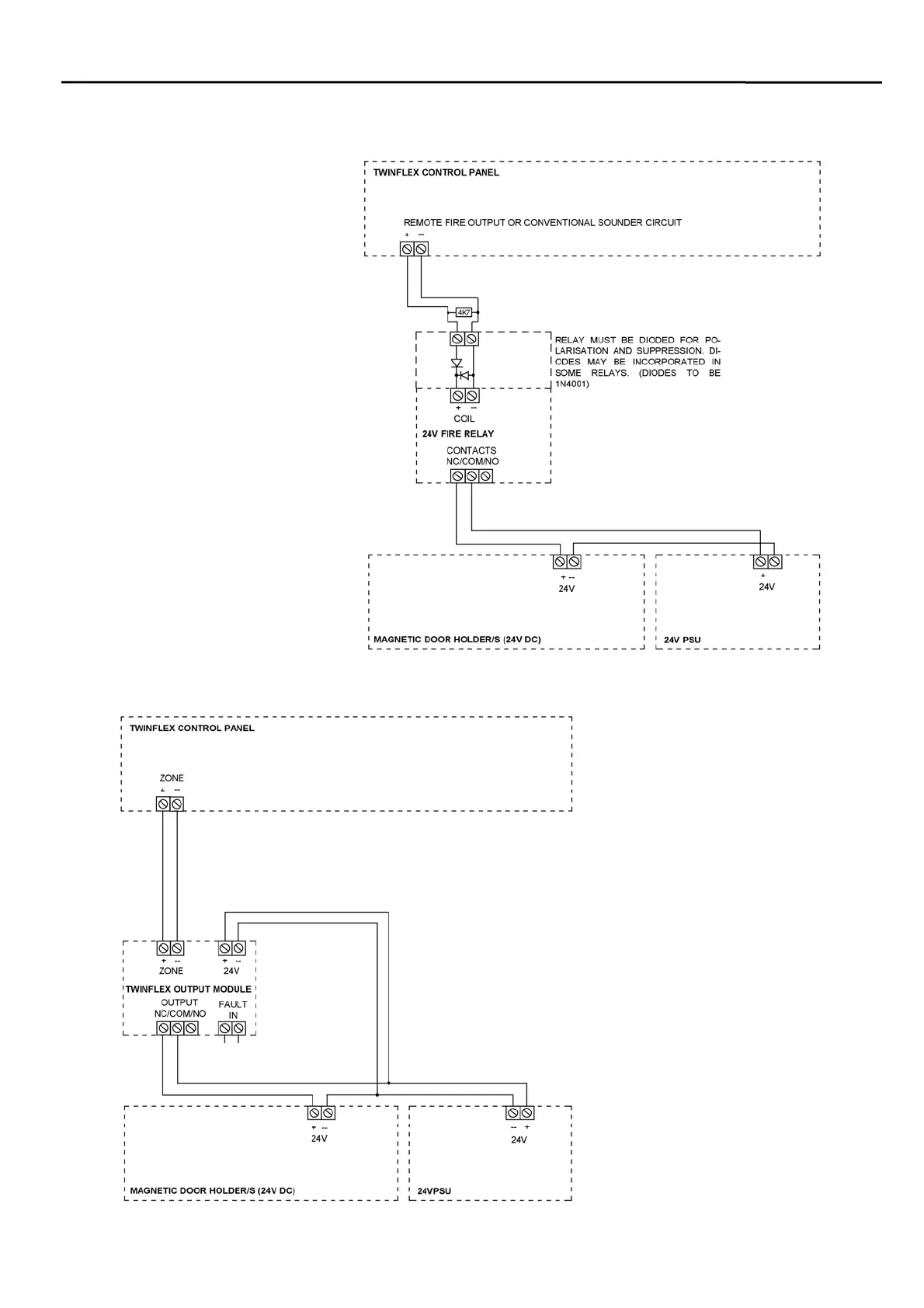
Magnetic Door Hold Units
If magnetic door hold devices
are required, it is
recommended that they are
connected as shown in the
upper right diagram. This is
suitable if it is convenient to
cable to the control panel.
We recommend the use of 24V
DC Magnetic Door Hold units,
in order to enable them to
operate from a power supply
with a battery standby. This
ensures normal operation in
the event of an interruption to
the power supply.
For assistance in choosing a
suitable power supply unit,
standby batteries, and
Magnetic Door Hold units
please contact your supplier.
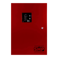
If this is not convenient, then the
lower left diagram shows how to
connect door hold magnets using
the Twinflex Output Module.
This may be sited on the two-wire
detection circuit, and does not need
to be cabled back to the control
panel if the zone extends to that
area.
The ‘Fault In’ circuit on the output
module should be connected to the
power supply unit fault contacts.
These need to be normally closed
circuit, and open circuit in the event
of a fault.