Twinflex V3 Control Panel Engineering and Commissioning Manual
43
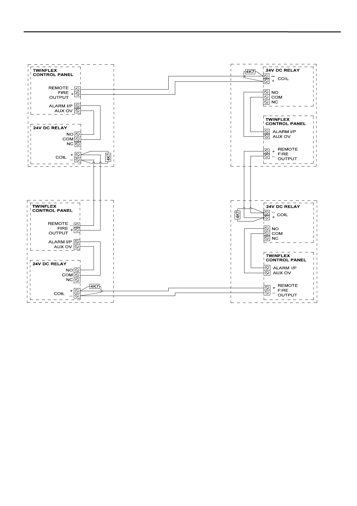
Connecting More Than Two Twinflex Control Panels Together
In order to interconnect a number of Twinflex control panels together connect them as shown above. This
will ensure that all cables are monitored, and system lock-up will be avoided.
This is suitable for all V3 control panels, and the V2 eight zone control panel. If any other versions of
Twinflex control panel are to be interlinked please contact your supplier for further details.
The control panel at which the alarm condition originated will show the relevant zonal fire indication.
Resetting this control panel will reset all control panels.
All other control panels will show common and remote fire indication only. These control panels may be
reset individually if required.
Ensure that the Remote Alarm Input is programmed for Mode 4 operation.
The configuration shown above will cause the entire system to reset when the panel in alarm is ‘Reset’. If it
is required that the system wide reset should follow the ‘Silence’ command then use the conventional
sounder circuit (Bell Output) instead of the Remote Fire Output.
Ensure that the relay is mounted
adjacent to the control panel as
shown, and that the cables are
routed directly within the housing
for protection.
The relays must be dioded for
polarisation and suppression.
These diodes should be marked
1N1004 or of a similar type, and
may be already located on the
relay PCB if it is designed for Fire
Alarm Systems. If the relay is a
general-purpose plug-in relay then
the diodes may need to be added
externally.
See the section entitled
‘Monitored Relays on the Remote
Fire Output’ for further details and
a drawing of how to connect them.