Twinflex V3 Control Panel Engineering and Commissioning Manual
8
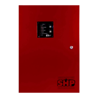
Power Supply Unit
The Fire Alarm Panel 230V AC supply requires fixed wiring between 0.75 mm
2
and 1.5 mm
2
, a 3 amp
fused un-switched spur with local isolation, to be terminated into the fused terminals provided in the back
box. On the 8 zone panel a metal cover, held in place with a locking nut, protects these terminals. The
mains supply should be dedicated to the Fire Alarm Panel and should be clearly labelled ‘FIRE ALARM:
DO NOT SWITCH OFF’ at all isolation points.
Note: The output of the power supply to zones, sounder outputs and auxiliary supply can vary between
21V and 32V.
The control panel requires standby sealed lead acid batteries to be installed according to the following
table. These are to be sited in the control panel back box in the provided enclosure. The batteries should
be connected in series using the connection leads supplied. See the section entitled Control Panel
Connections for panel connections.
Control Panel Standby Requirements Batteries required
All 2 or 4 zone panels 24 hours & 30 minutes in
alarm
2 x 12v 2.1 Ah
All 2 or 4 zone panels 72 hours & 30 minutes in
alarm
2 x 12v 2.1 Ah
All 8 zone panels 24 hours & 30 minutes in
alarm
2 x 12v 3.2 (or 3.3) Ah
All 8 zone panels 72 hours & 30 minutes in
alarm
2 x 12v 7.2 Ah
Note that the charging circuit will be in its high impedance state (approximately 3V DC) if no batteries,
faulty batteries or only one battery is connected. The full 27V DC charging voltage should be present if the
correct batteries are connected.
If the system shows a charger or battery fault on first power up, leave the system to charge its batteries for
5-6 hours.
In order to test for correct operation of the batteries, remove the mains 230V AC fuse and allow the
batteries to settle from their charging voltage for approximately 5 minutes. The battery voltage should then
be measured using an electronic test meter and a voltage greater than 24V DC should be seen.
Note that batteries are electrically live at all times and great care should be taken to ensure that the
terminals are never presented with a short circuit. Care should be taken at all times, especially during
transit, installation and normal use.
Batteries no longer required should be disposed of in a safe and environmentally friendly manner by the
manufacturer or a suitable recycling service. They should never be incinerated or placed in normal rubbish
collection facilities.