Twinflex V3 Control Panel Engineering and Commissioning Manual
31
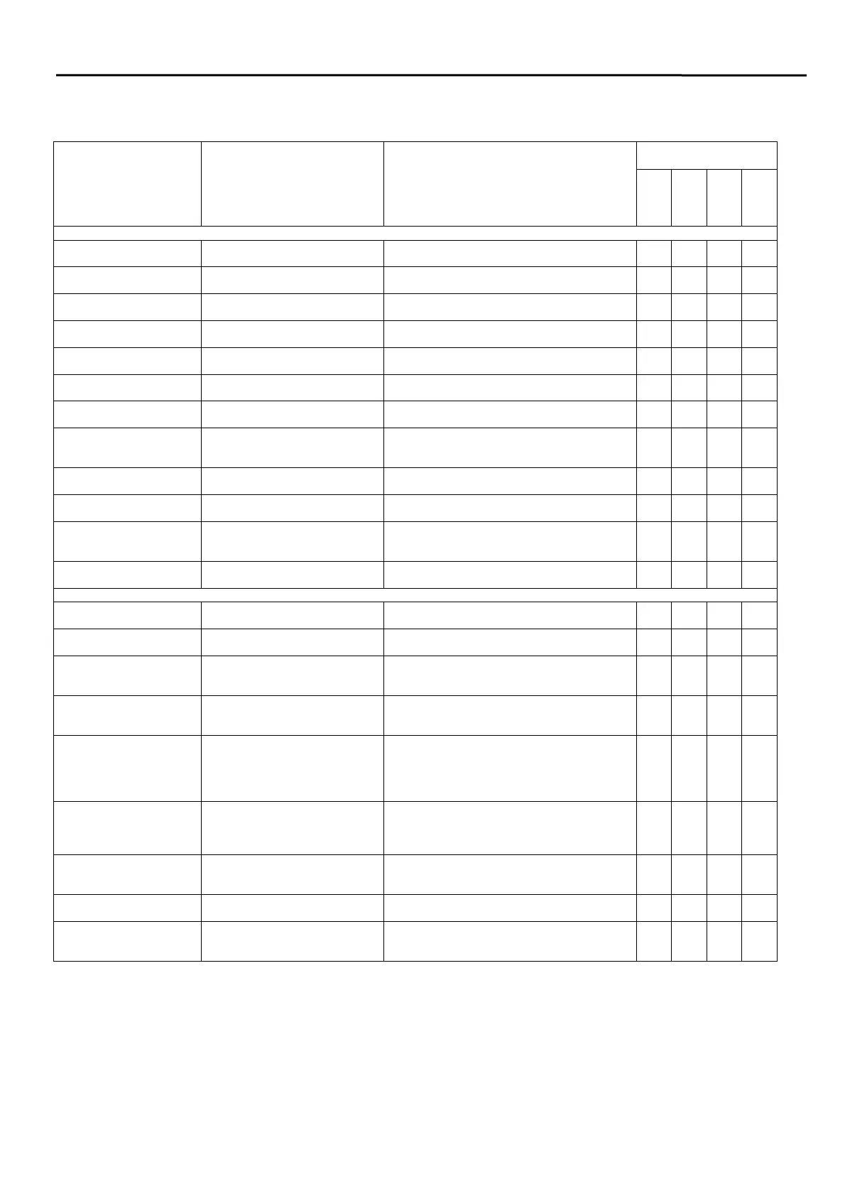
Programming Summary
Description
Action
Notes
Relevant Panels and
Modes of Operation
Access Level 2 – ‘User’ (These functions are described on the control panel overlay adjacent to the relevant button)
Enter ‘AL2’ (User) from
‘AL1’ (Normal)
‘Access’ ‘514. Controls Enabled Light will come on
continuously.
Enter ‘AL2’ (User) from
‘AL1’ (Normal)
Turn key on. Controls Enabled Light will come on
continuously.
Exit ‘AL2’ (User) to ‘AL1’
(Normal)
‘Access’ ‘514’. Controls Enabled Light will go off.
Exit ‘AL2’ (User) to ‘AL1’
(Normal)
Turn key off Controls Enabled Light will go off.
Silence the alarm
sounders
‘Silence’ The alarm sounders will silence.
Reset the control panel to
clear activations
‘Reset’ The control panel will reset if all devices are
free of alarm.
Silence the fault buzzer
until a further fault occurs
‘Silence Buzzer’ The buzzer will silence and the ‘Buzzer
Silenced’ light will come on.
Set or remove a zone
from ‘Test Mode’
‘Test Zone’ followed by the
number of the required zone, ie,
‘3’.
The zone ‘Fault/disable/test’ light and the
general ‘Test’ light will come on or go off
accordingly.
Disable or enable the
Remote Fire Output
‘Access’ & ‘Disable Remote
Fire’
The ‘Remote Fire’ ‘Fault/Disable’ light will
come on or go off accordingly.
Disable or enable the
alarm sounders
‘Access’ & ‘Disable Alarms’ The ‘Alarms Disabled’ light will come on or go
off accordingly.
Disable or enable a Zone ‘Access’ & ‘Disable Zone’,
followed by the zone number
required, ie ‘3’
The ‘Disabled’ light and the relevant
‘Fault/disable/test’ light will come on or go off
accordingly.
Lamp Test ‘Lamp Test’, and hold for 5
seconds
All the lights will come on until the ‘Lamp Test’
button is released
Access Level 3 - ‘Engineer’ (The functions override those described on the control panel overlay)
Enter ‘AL3’ (Engineer)
from ‘A2’ (User)
‘Access’ 5244 Controls Enabled Light will flash and buzzer
will pulse.
Exit ‘AL3’ (Engineer) to
‘AL2’ (User)
‘Access’ Controls Enabled Light will come on
continuously.
Program the number of
active zones
‘1’ followed by the number of
zones required, ie ‘3’ for zones
1, 2 & 3 active.
The zone lights will show the existing setting
before the zone selection is made. The panel
will turn off the unused zones
Alarm Configuration ‘3’ followed by;
’1’ - common alarm or,
‘2’ - 2 stage alarm
The zone lights will show the existing setting
before the selection is made;
Alarm Input Configuration ‘5’ followed by;
’1’ - timed class change,
‘2’ - remote fire, no output
‘3’ - class change
‘4’ - remote fire
The zone lights will show the existing setting
before the selection is made;
Zone Mode ‘Access’ & ‘1’, followed by the
zone number requiring a change
of state, ie ‘3’
The zone lights will show the existing setting
before the zone selection is made;
Zone light on – Dwelling Zone
Zone light off – Communal Zone
Repeater Configuration ‘Access’ & ‘2’, followed by; ’1’ –
Fire alarm outputs,
‘2’ – Confirmation outputs
The zone lights will show the existing setting
before the zone selection is made;
Confirmation Time ‘Access’ & ‘3’, followed by 1-5
minutes, ie ‘2’
The zone lights will show the existing setting
before the zone selection is made;
Disable or enable a Zone ‘Access’ & ‘5’, followed by the
zone number required, ie ‘3’
The ‘Disabled’ light and the relevant
‘Fault/disable/test’ light will come on or go off
accordingly.
2/4 zone
8 zone
Standard
Plus
 Loading...